Threaded rod plunger installation tool

a plunger and installation tool technology, applied in the field of plungers, can solve the problems of heavy weight, high labor intensity, and potentially unsafe personnel, and achieve the effects of less damage to parts, less time-consuming, and less time-consuming

Inactive Publication Date: 2013-04-16
S P M FLOW CONTROL
View PDF19 Cites 18 Cited by
  • Summary
  • Abstract
  • Description
  • Claims
  • Application Information

AI Technical Summary

Benefits of technology

[0009]During installation of the plunger the plunger is placed at the cylinder opening and the threaded rod plunger installation tool is mounted onto the pump. A driver such as a wrench or a motorized drill can engage the bolt head and rotate it and thereby advance the threaded rod into the cylinder opening. The nut prevents the threaded rod from backing out as it pushes the plunger into the cylinder bore. The installation tool advantageously generates sufficient force, in one example at least 2000 psi, to push the plunger into place. Once the plunger is properly in place within the pump cylinder, the threaded rod can be backed out of the nut by the driver and the plunger installation tool can then be removed for storage, allowing the suction cover plate to be placed back on the cylinder opening.
[0010]The threaded rod plunger installation tool thus advantageously provides a safer way to maintain and disassemble pumps because the plunger installation tool, rather than a hammer, can be used to push the plunger back into position within the pump cylinder. This also results in a less time consuming, potentially less damaged parts, and a less labor intensive method of maintaining and disassembling the pumps as hammering of the heavy plunger is eliminated.

Problems solved by technology

The plunger is heavy and requires much effort to push it back into the cylinder through the packing elements.
Frequently, installing the plunger requires maintenance personnel to hammer the plunger into place during installation, potentially damaging pump parts or injuring personnel.
Thus, installation of the plunger into the cylinder is time consuming, labor intensive, and potentially unsafe to personnel.

Method used


Image

  • Threaded rod plunger installation tool
  • Threaded rod plunger installation tool
  • Threaded rod plunger installation tool

Examples


Embodiment Construction

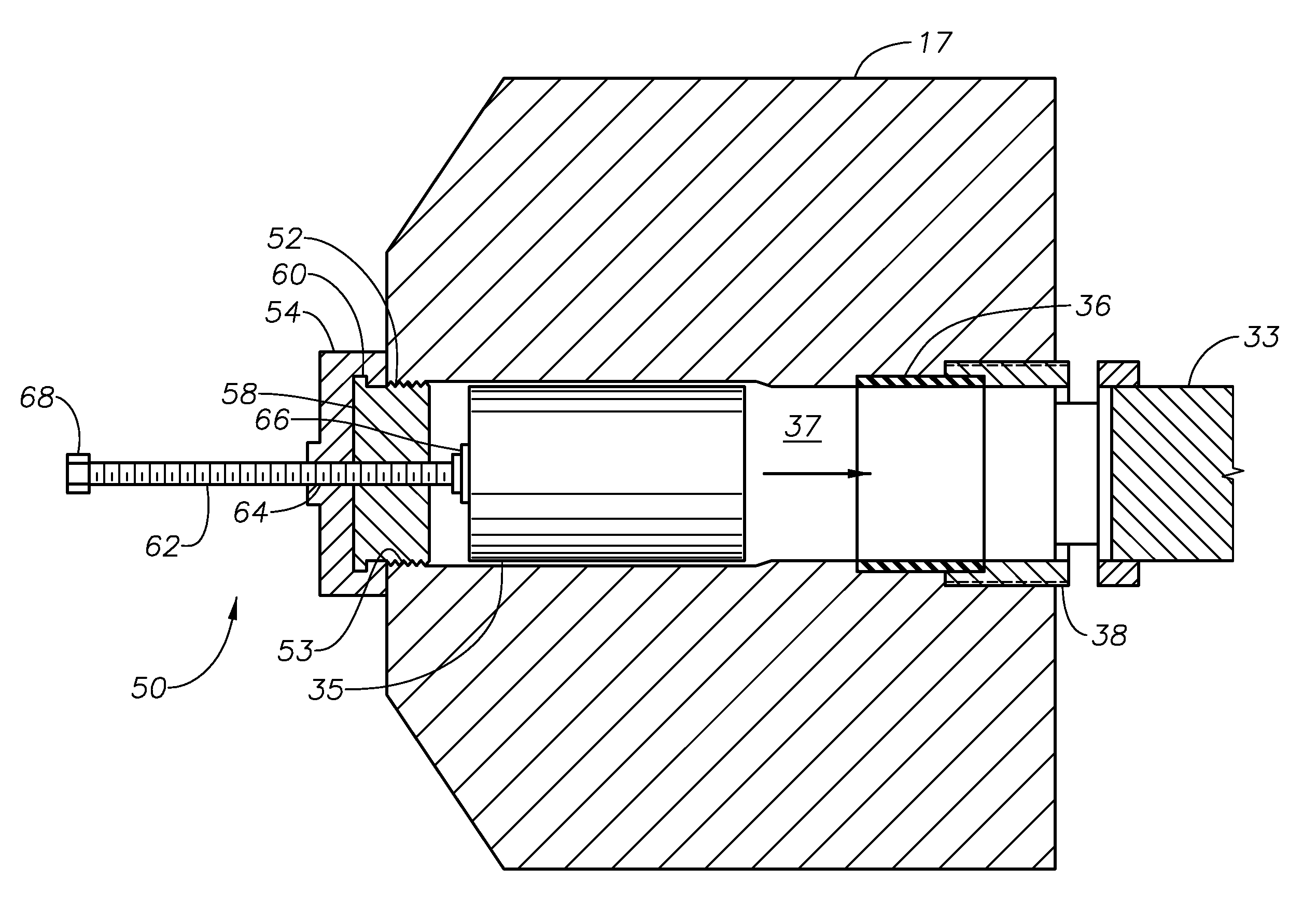
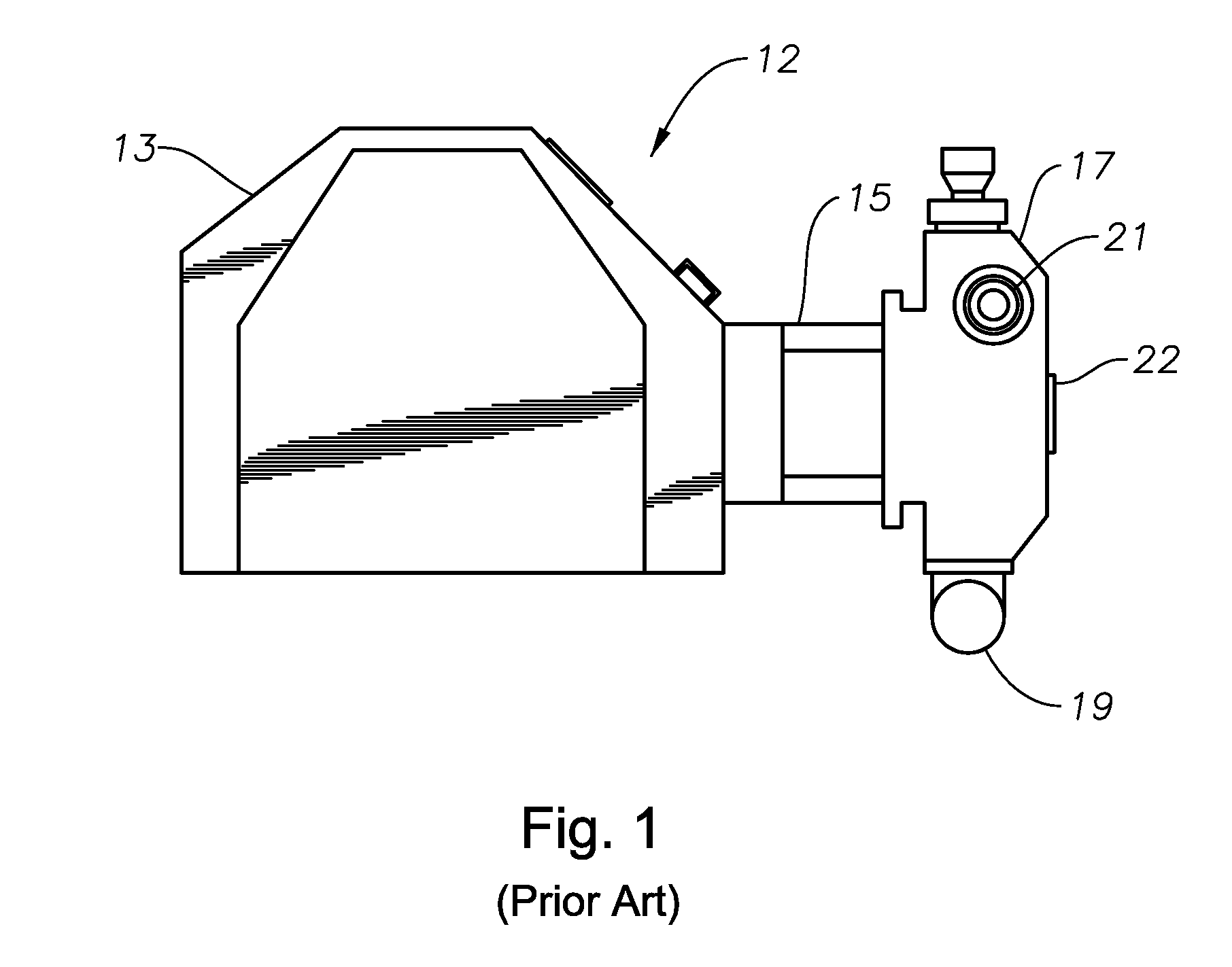
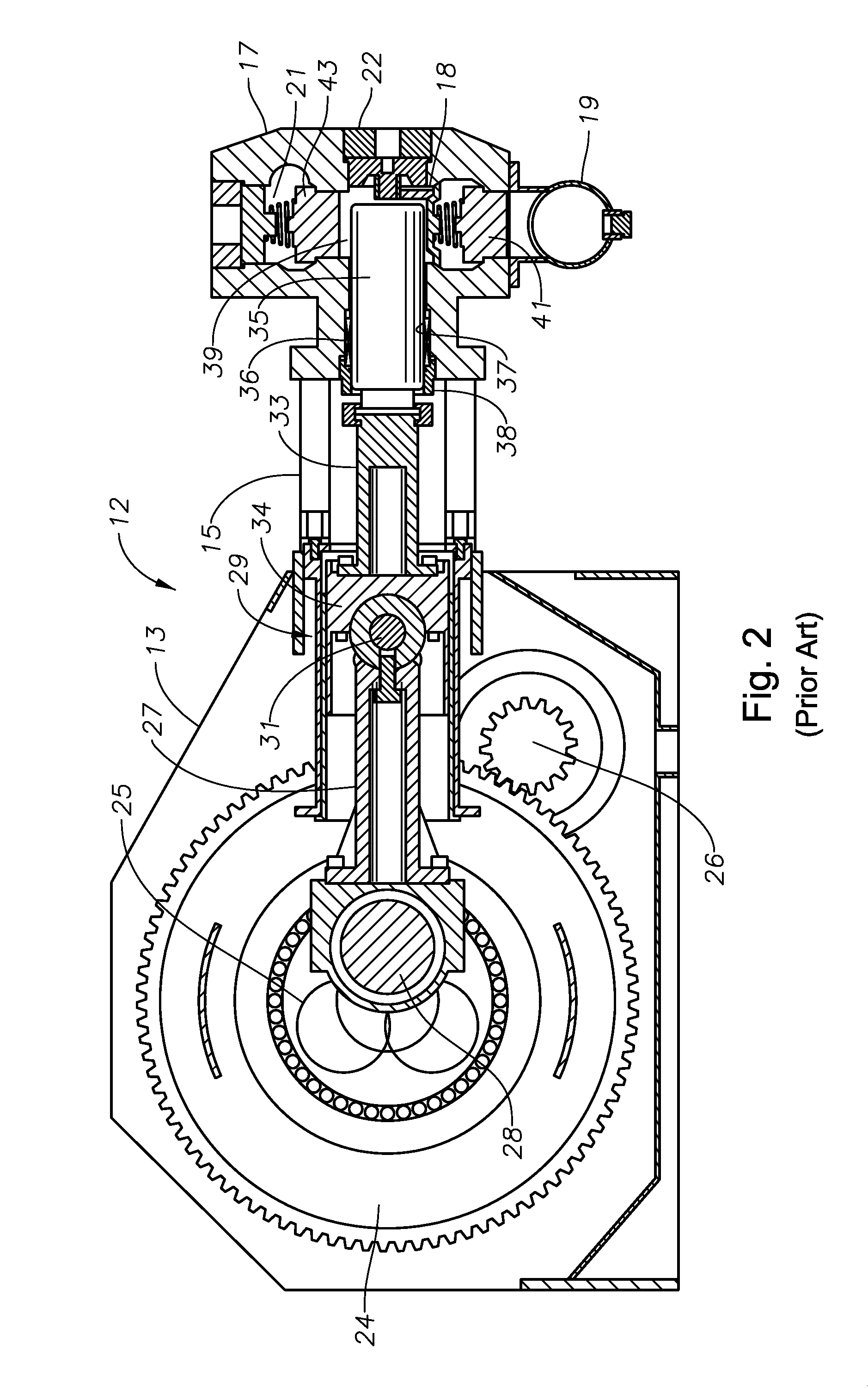
[0016]Referring to FIGS. 1 and 2, reciprocating pump assembly or pump 12 includes a crankshaft housing 13 that comprises a majority of the outer surface of reciprocating pump 12. Stay rods 15 connect crankshaft housing 13 to a cylinder housing 17 having a set of cylinders 37 (FIG. 2). Each cylinder 37 is in communication with a fluid inlet 19 and a fluid outlet 21. As shown in FIG. 2, a suction cover plate 22 connects to an end of each cylinder 17 opposite the housing that houses the stay rods 15. Pump 12 can be free-standing on the ground, can be mounted to a trailer that can be towed between operational sites, or mounted to a skid such as for offshore operations.

[0017]Referring to FIG. 2, a portion of reciprocating pump 12 housed within crankshaft housing 13 is shown. Crankshaft housing 13 houses a crankshaft 25, which is typically mechanically connected to a motor (not shown). The motor rotates crankshaft 25 in order to drive reciprocating pump 12 (FIG. 1). In one embodiment, cra...


PUM

PropertyMeasurementUnit
outer diameteraaaaaaaaaa
lengthaaaaaaaaaa
diameteraaaaaaaaaa

Abstract

A plunger installation tool that exerts a force on a plunger for a reciprocating pump to install the plunger into a pump cylinder opening. Maintenance of the pump typically includes repacking of the packing that surrounds the plunger and revalving of the pump's inlet and outlet valve. To allow repacking or revalving, the pump is disassembled and the plunger is removed. The plunger installation tool threads onto the pump cylinder opening to provide a reaction point for a threaded rod that is driven at one end by a driver and engages the plunger at an opposite end during installation to push the plunger into the cylinder opening without the use of hammers by personnel.

Description

CROSS-REFERENCE TO RELATED APPLICATION[0001]This application claims priority to provisional application 61 / 225,142, filed Jul. 13, 2009.FIELD OF THE INVENTION[0002]This invention relates in general to plungers used in reciprocating pumps, and, in particular, to a threaded rod tool for installing a plunger.BACKGROUND OF THE INVENTION[0003]Various kinds of pumps can be used in oilfield operations. One type of pump, for example, is a reciprocating pump. The reciprocating pump can be used to pump fluid such as chemicals, cement, or other media into a well. Reciprocating pumps typically increase the pressure within a cylinder by reciprocating a plunger longitudinally within the cylinder. Packing is generally used around the plunger and the plunger reciprocates as a crankshaft located within the pump rotates. As the plunger moves away from the cylinder, the pressure of the fluid inside chamber decreases creating a differential pressure across an inlet valve that allows the fluid to enter ...

Claims


Application Information

Patent Timeline
Patent Type & Authority Patents(United States)
IPC IPC(8): B23P15/00
CPCF04B53/22F04B23/00Y10T29/49826Y10T29/49236Y10T29/53891Y10T29/53Y10T29/53848Y10T29/53952Y10T29/49231Y10T29/49229
Inventor PATEL, PANKAJ
Owner S P M FLOW CONTROL
Why Eureka
Try Eureka