Synthetic aperture processing system and synthetc aperture processing method

a processing system and synthetic aperture technology, applied in the direction of instruments, measurement devices, using reradiation, etc., can solve the problem of low resolution along the travel line (azimuth direction) of platforms, and achieve the effect of low computation load and high precision

Inactive Publication Date: 2013-04-16
JAPAN AGENCY FOR MARINE-EARTH SCIENCE AND TECHNOLOGY
View PDF6 Cites 4 Cited by
  • Summary
  • Abstract
  • Description
  • Claims
  • Application Information

AI Technical Summary

Benefits of technology

[0020]In accordance with the synthetic aperture processing system and the synthetic aperture processing method of the present invention, synthetic aperture processing can be performed at high precision with low computation load.

Problems solved by technology

Unfortunately, they have low resolutions along the travel line (azimuth direction) of platforms with the sonars and radars in the exploration of distant targets.

Method used


Image

  • Synthetic aperture processing system and synthetc aperture processing method
  • Synthetic aperture processing system and synthetc aperture processing method
  • Synthetic aperture processing system and synthetc aperture processing method

Examples


first embodiment

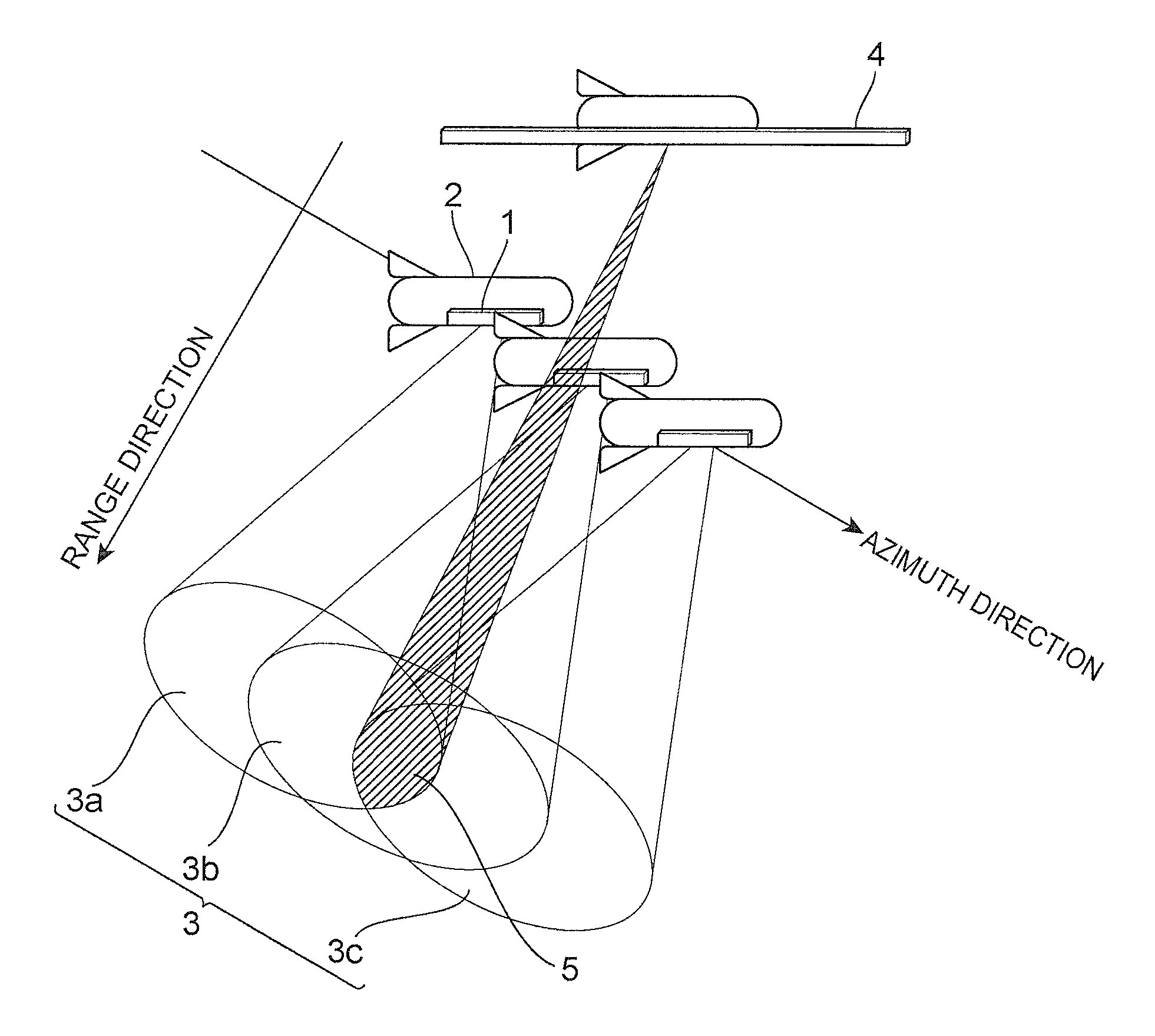
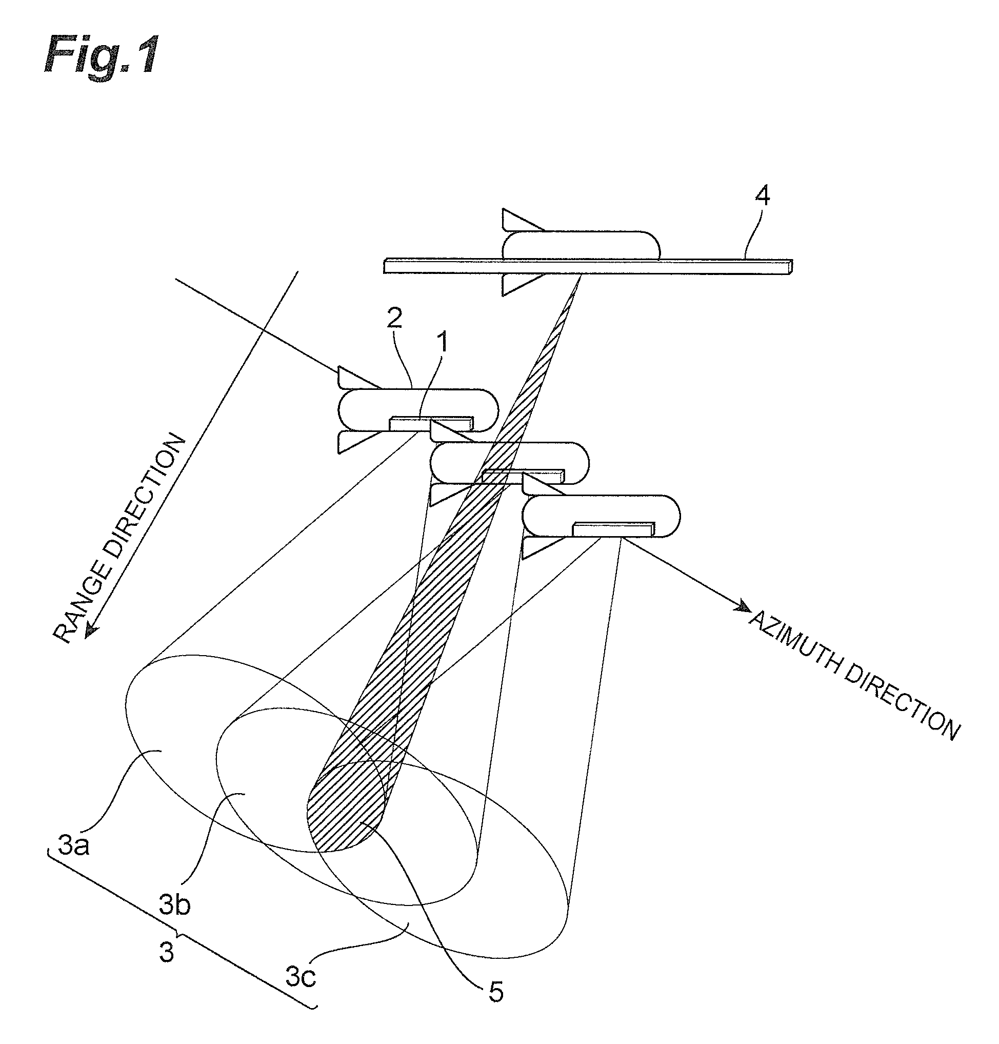
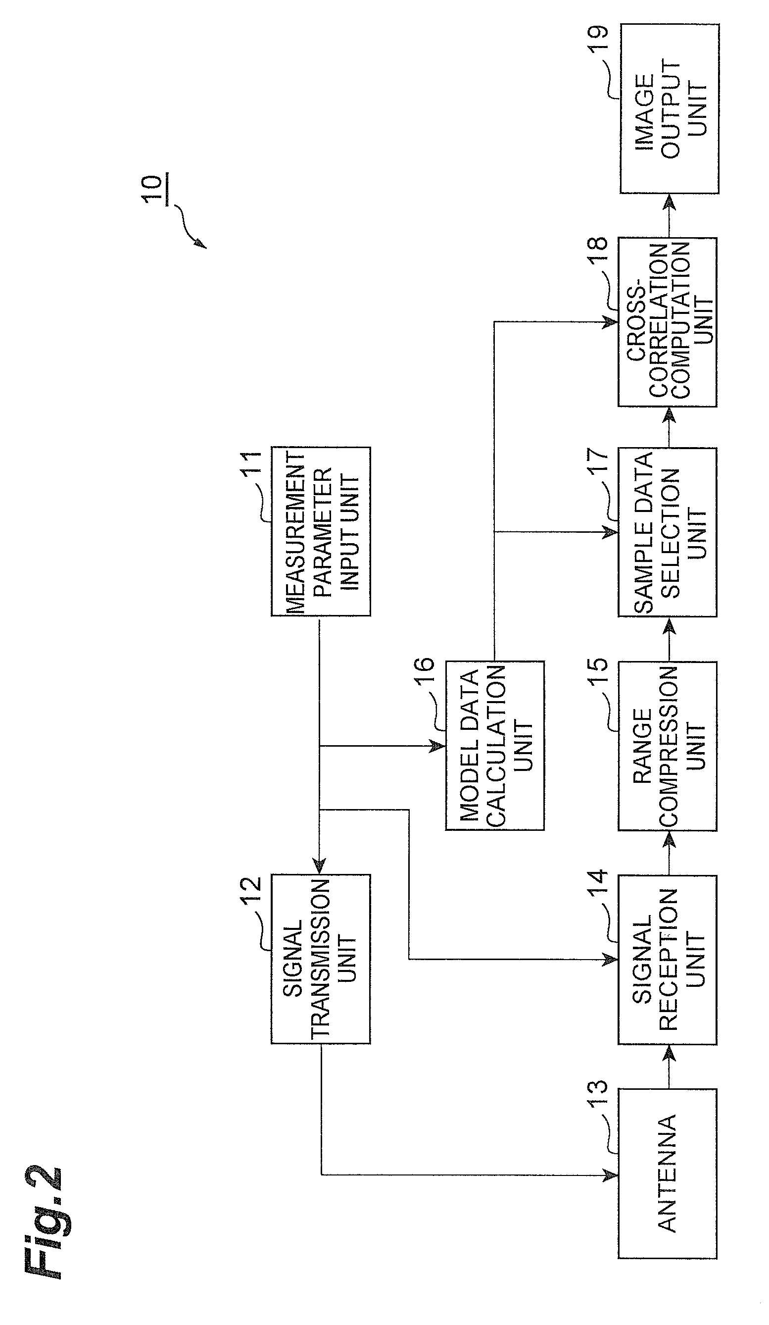
[0051]A first embodiment of the synthetic aperture processing system in accordance with the present invention is described below. FIG. 2 illustrates the configuration of the synthetic aperture processing system in accordance with the first embodiment of the present invention. As illustrated in FIG. 2, the synthetic aperture processing system 10 of the present embodiment includes a measurement parameter input unit 11, a signal transmission unit (transmission means) 12, an antenna (transmission means and reception means) 13, a signal reception unit (reception means) 14, range compression unit (range compression means) 15, a model data calculation unit (model data calculation means) 16, a sample data selection unit (correlation value calculation means and selection means) 17, a cross-correlation computation unit (correlation value calculation means and cross-correlation computation means) 18, an image output unit (output means) 19.

[0052]The components other than the antenna 13 of the s...

second embodiment

[0084]A second embodiment of the synthetic aperture processing system in accordance with the present invention is described below. FIG. 12 illustrates the configuration of the synthetic aperture processing system in accordance with the second embodiment of the present invention. As illustrated in FIG. 12, the synthetic aperture processing system 20 of the present embodiment computes the cross-correlation values with model data using all the reception data without extracting the sample data from the reception data generated by the range compression unit 15, unlike the synthetic aperture processing system 10 in FIG. 2.

[0085]In the synthetic aperture processing system 20, the function blocks of the measurement parameter input unit 11, the signal transmission unit 12, the signal reception unit 14, the range compression unit 15, and the image output unit 19 are the same as those of the units in the synthetic aperture processing system 10 in FIG. 2.

[0086]A model data calculation unit 26 p...

third embodiment

[0090]A third embodiment of the synthetic aperture processing system in accordance with the present invention is described below. FIG. 13 illustrates the configuration of the synthetic aperture processing system in accordance with the third embodiment of the present invention. As illustrated in FIG. 13, the synthetic aperture processing system 30 of the present embodiment does not perform the cross-correlation computation between the sample data segments selected by the sample data selection unit 17 and the model data segments, but performs simple summation computation to calculate the correlation values, unlike the synthetic aperture processing system 10 in FIG. 2.

[0091]In the synthetic aperture processing system 30, the function blocks of the measurement parameter input unit 11, the signal transmission unit 12, the antenna 13, the signal reception unit 14, the range compression unit 15, the model data calculation unit 16 and the image output unit 19 are the same as those of the un...


PUM


Abstract

A synthetic aperture processing system that includes a signal transmission unit for generating and radiating a plurality of chirp waves to an irradiation region from measuring sites, a signal reception unit for receiving a plurality of reflected waves caused by the plurality of chirp waves, a range compression unit for range-compressing each of the reflected waves and generating reception data consisting of sinc functions, a cross-correlation computation unit for, based on a plurality of model data segments, calculating correlation values representing a degree of correlation between each of the model data segments and the reception data, and image output unit for outputting the correlation values calculated by cross-correlation computation unit.

Description

TECHNICAL FIELD[0001]The present invention relates to a synthetic aperture processing system and a synthetic aperture processing method in, for example, radars and sonars.BACKGROUND ART[0002]Sonars and radars can explore distant targets in wide ranges. Unfortunately, they have low resolutions along the travel line (azimuth direction) of platforms with the sonars and radars in the exploration of distant targets. A synthetic aperture processing method is known for overcoming such a disadvantage in which a virtual extension of a short receiving array of a readily manageable size enhances the azimuth resolution.[0003]In the synthetic aperture processing, while moving at a constant speed, the platform repeatedly radiates periodic pulses toward the ground or sea surface to receive a plurality of reflected waves. Subsequently, processing of these refection waves creates sonar images or radar images with improved resolutions in both the range direction (direction of the pulse-irradiated gro...

Claims


Application Information

Patent Timeline
Patent Type & Authority Patents(United States)
IPC IPC(8): G01S13/00
CPCG01S13/9017G01S15/8904G01S15/104G01S13/282
Inventor SAWA, TAKAO
Owner JAPAN AGENCY FOR MARINE-EARTH SCIENCE AND TECHNOLOGY
Why Eureka
Try Eureka