

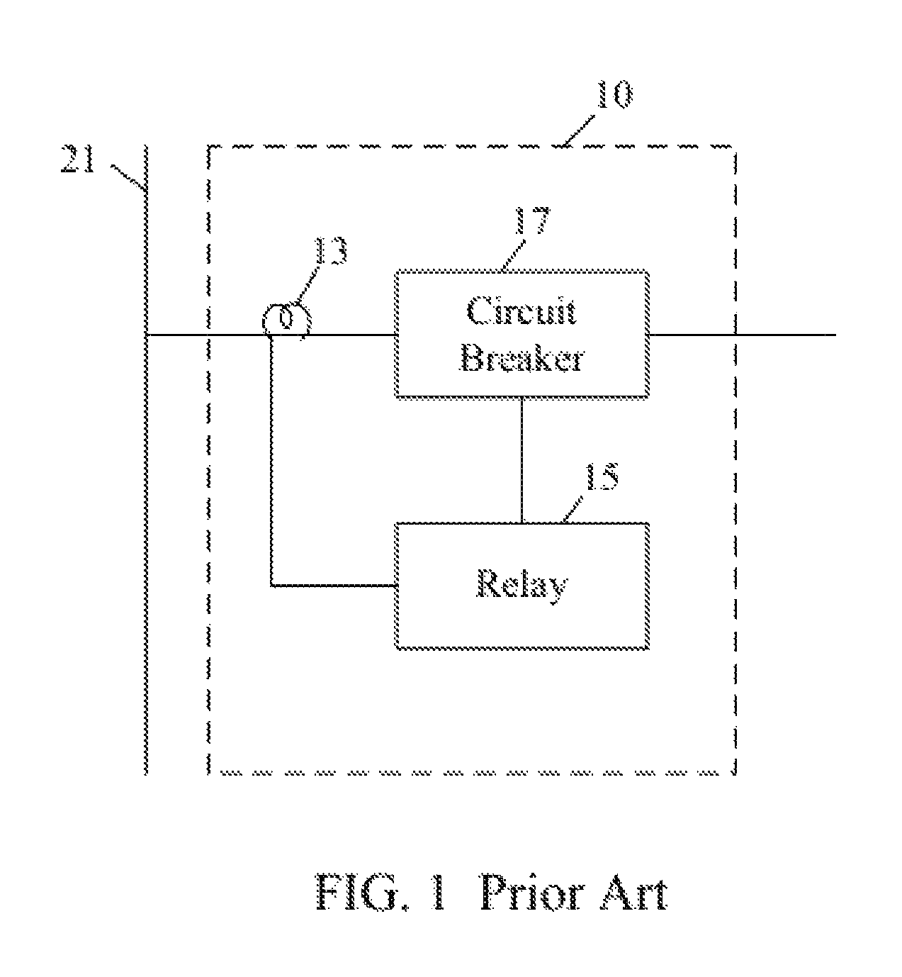
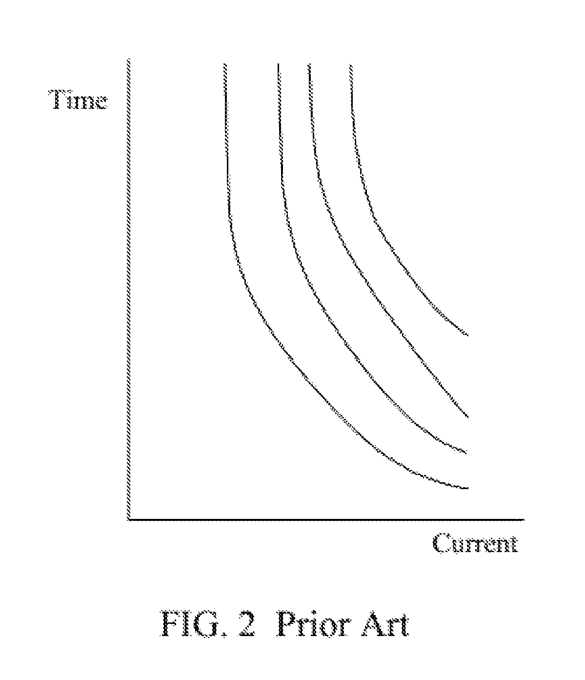
Overcurrent relay
a relay and overcurrent technology, applied in emergency protective arrangements for limiting excess voltage/current, measurement using ac-dc conversion, instruments, etc., can solve the problems of time delay to the cut-off of the circuit breaker, improper circuit breaker operation, and power supply quality and system safety
- Summary
- Abstract
- Description
- Claims
- Application Information
AI Technical Summary
Benefits of technology
Problems solved by technology
Method used
Image

Examples
Embodiment Construction
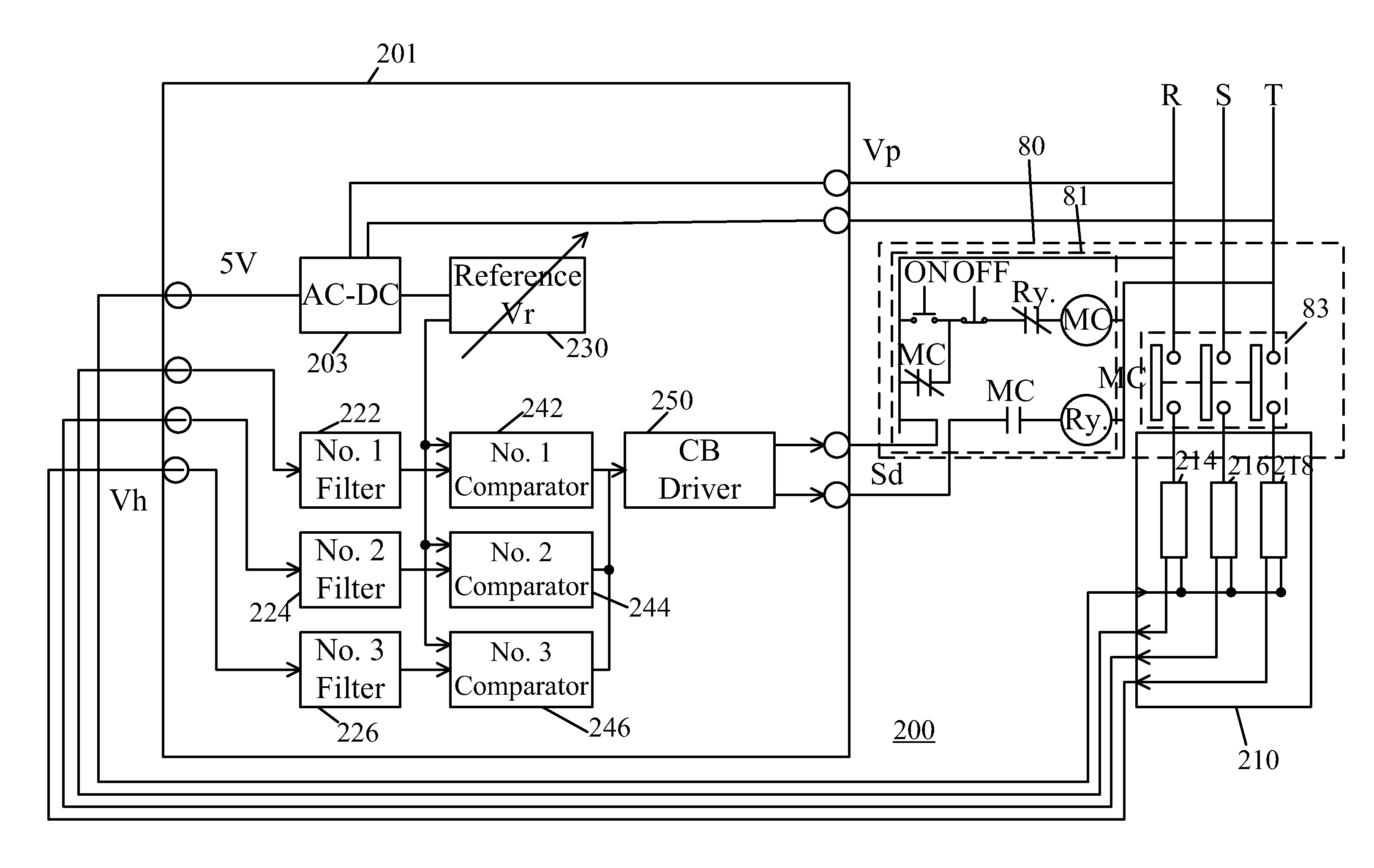
[0027]The present invention utilizes at least one Hall sensor to detect a failure current so as to avoid using a current transformer (CT). Accordingly, the time delay problem due to the CT saturation can be eliminated.
[0028]FIG. 5 is a schematic block diagram showing an overcurrent relay 100 in accordance with an embodiment of the present invention. The overcurrent relay 100 has a Hall sensor 110 for detecting a failure current from a power line or the like. The Hall sensor is a widely known device. The Hall sensor senses a magnetic flux density due to a current flowing in a power system and generates a Hall field, and thereby a Hall voltage signal can be obtained. The Hall sensor 110 transfers a sensed current into a Hall voltage. The Hall sensor 110 has no iron core, and therefore no distortion will occur even when the amplitude of the failure current is very great. FIG. 6 shows a failure current waveform 61 sensed by the conventional CT and a failure current waveform 63 sensed by...
PUM
 Abstract
Description
Claims
Application Information