
Double suction type sterilizing vacuum cleaner

a vacuum cleaner and suction port technology, applied in the field of vacuum cleaners, can solve the problems of difficult for users to quickly release the soft cleaning object from the suction port, adverse effects on the lifetime of the motor b>94/b>, etc., and achieve the effect of reducing the overheating phenomenon of the motor, reducing the sucking pressure, and facilitating the release of the blocking situation

Active Publication Date: 2013-04-23
YEJEN APPLIANCES SHENZHEN
View PDF1 Cites 13 Cited by
  • Summary
  • Abstract
  • Description
  • Claims
  • Application Information

AI Technical Summary

Benefits of technology

"The present invention is a sterilizing vacuum cleaner with double suction ports. The main technical effect of this invention is that when the main suction port is blocked, there is still another suction port that allows air flow to be introduced into the vacuum cleaner so as to reduce sucking pressure at the main suction port. This makes it easier for the user to release the blocking situation at the main suction port while effectively reducing overheating phenomenon of a motor of the vacuum cleaner. Additionally, the vacuum cleaner includes a sterilizing lamp and a dust collecting box with a secondary suction port for introducing ambient air into the air channel. This allows the user to release the blocking situation at the main suction port when the main suction port is blocked. The dust collecting box also includes a hollow body, a flow guiding cover, and a valve sheet for controlling the air flow. The flow guiding cover also includes a grid piece with at least one flow opening and an adjustment piece for adjusting the air flow."

Problems solved by technology

When suction port 91 is totally blocked, it is difficult for a user to quickly release the soft cleaning object from the suction port 91.
In the blocking period, the circulation of an air flow in the vacuum cleaner is not smooth so that an overheating phenomenon may be caused in the motor 94, and the lifetime of the motor 94 is adversely affected.

Method used


Image

  • Double suction type sterilizing vacuum cleaner
  • Double suction type sterilizing vacuum cleaner
  • Double suction type sterilizing vacuum cleaner

Examples


Embodiment Construction

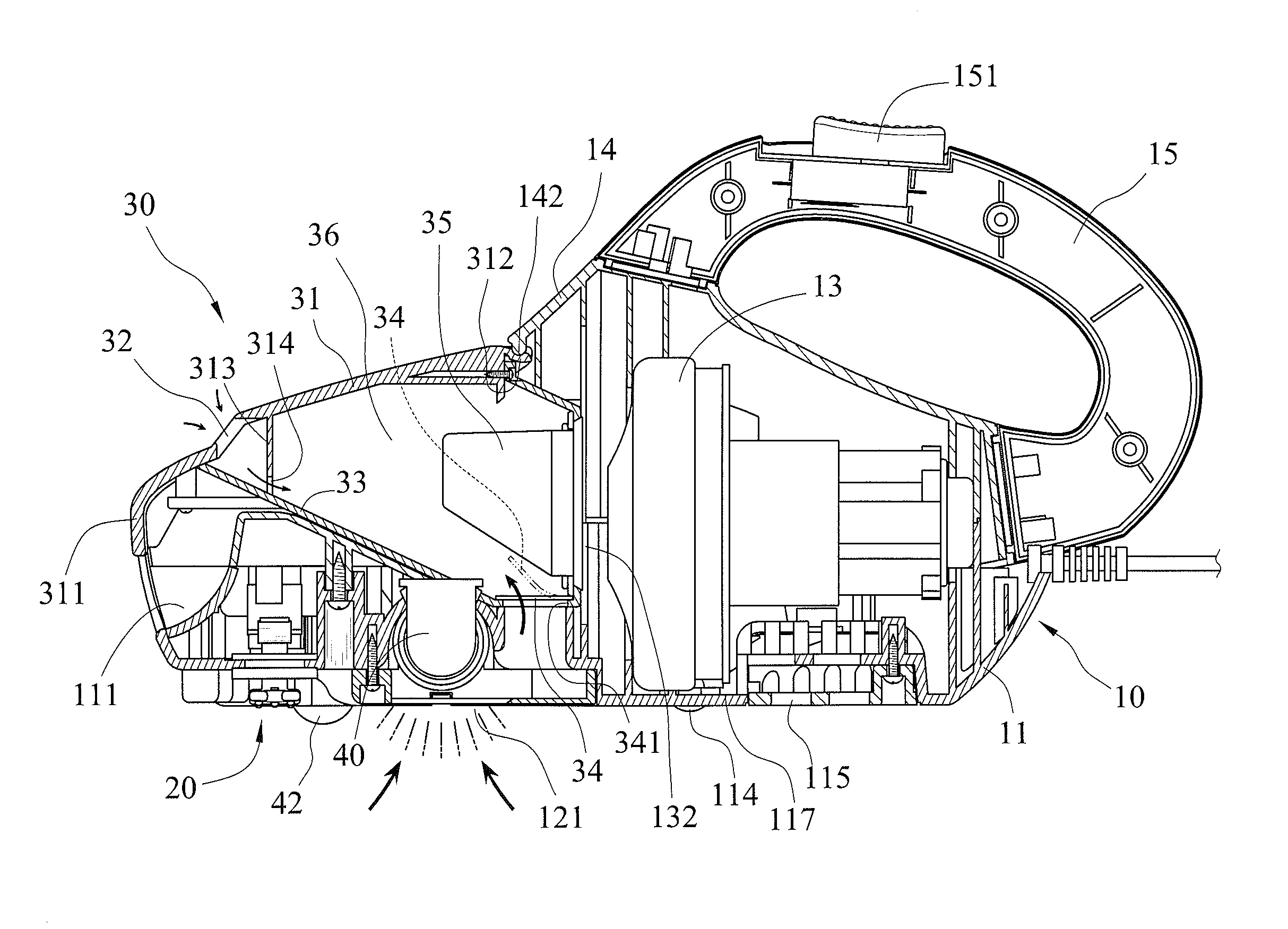
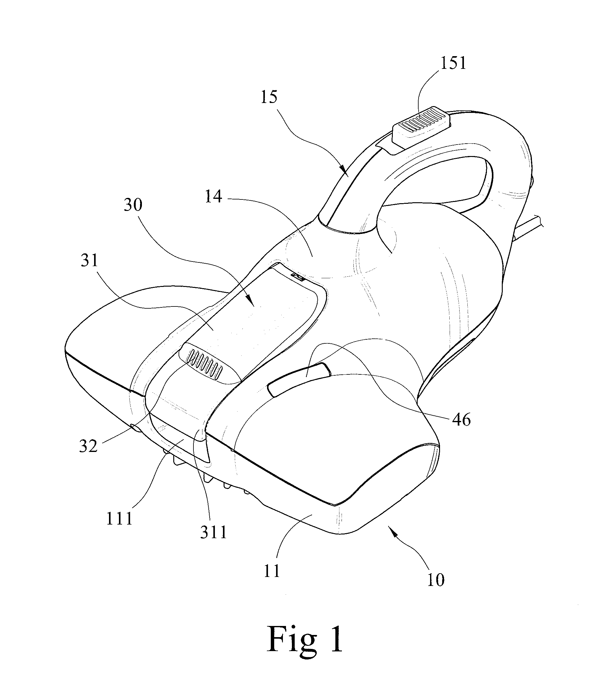
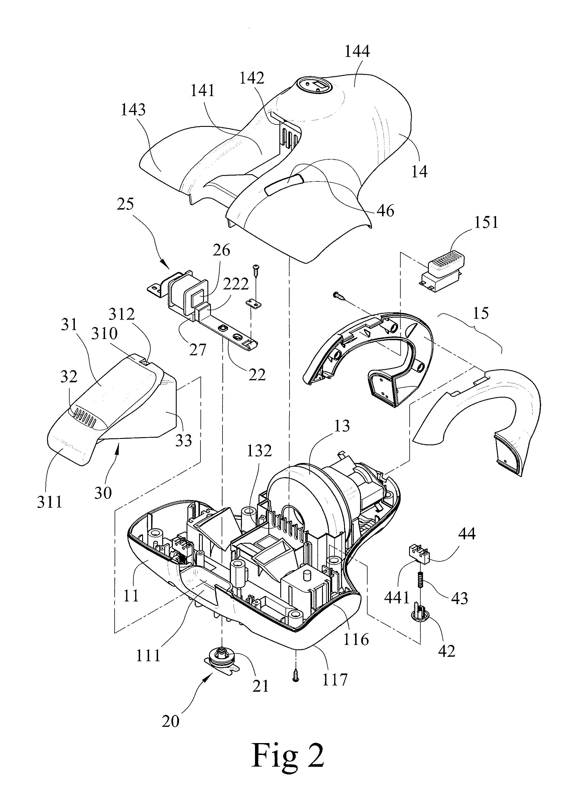
[0023]A double suction type sterilizing vacuum cleaner of a first embodiment of the present invention is shown in FIGS. 1 through 8 of the drawings and generally designated 10. The vacuum cleaner 10 includes a base seat 11, an upper cover 14, a hitting device 20, a sterilizing lamp 40, and a dust collecting box 30.

[0024]The base seat 11 includes upper and lower sides 116 and 117 spaced in a vertical direction. Base seat 11 further includes a first recess 111 formed in a front side thereof, a second recess 112 formed in lower side 117, and a third recess 113 formed in lower side 117 and spaced from the second recess 112 (see FIG. 3). A bottom cover 12 covers third recess 113 and includes a plurality of holes forming a main suction port 121. A plurality of wheels 114 is installed on lower side 117 of base seat 11. A motor 13 is installed in a rear side of base seat 11 for generating a suction force. Several flow slots 132 are provided in upper side 116 of base seat 11 and located adja...


PUM


Abstract

A double suction type sterilizing vacuum cleaner includes a base seat and an upper cover mounted on an upper side of the base seat. A main suction port is provided in the base seat. A hitting device is mounted on the base seat and adapted to hit a cleaning object under the base seat. A sterilizing lamp is mounted in the base seat for sterilizing purposes. A dust collecting box is detachably mounted to the upper cover and defines an air channel in communication with the main suction port. A secondary suction port is provided in the dust collecting box and in communication with the air channel. When the main suction port is blocked, an ambient air can be supplied to the air channel through the secondary suction port, facilitating the release of the blocking situation in the main suction port.

Description

BACKGROUND OF THE INVENTION[0001]1. Field of the Invention[0002]The present invention relates to a vacuum cleaner and, more particularly, to a sterilizing vacuum cleaner with double suction ports.[0003]2. Description of the Related Art[0004]Vacuum cleaners are frequently used for cleaning and removing dust. The vacuum cleaners for bed clothes such as comforters are generally installed with hitting and sterilizing devices. The hitting device bobs bed clothes so that the dust on the bed clothes flies up and then is sucked in through a suction force generated by a motor. The sterilizing device emits ultraviolet rays to the dust so as to sterilize small pests in the dust.[0005]FIG. 10 shows a conventional vacuum cleaner including a main body 90. The main body 90 is provided with a suction port 91, a first sterilizing portion 92, a second sterilizing portion 93, a motor 94, a third sterilizing portion 95, and a discharge port 96. When a bed clothes such as comforter is cleaned, an ambien...

Claims


Application Information

Patent Timeline
Patent Type & Authority Patents(United States)
IPC IPC(8): A47L5/00
CPCA47L5/24A47L7/04A47L9/0072
Inventor HSU, PET-CHENG
Owner YEJEN APPLIANCES SHENZHEN
Learn More