
Pouch type case and battery pack including the same

a battery pack and pouch technology, applied in the direction of batteries, sustainable manufacturing/processing, cell components, etc., can solve the problems of reducing the utilization rate of space, affecting the efficiency of production, so as to reduce the internal dead space and maximize the utilization rate.

Active Publication Date: 2013-04-23
LG ENERGY SOLUTION LTD
View PDF17 Cites 11 Cited by
  • Summary
  • Abstract
  • Description
  • Claims
  • Application Information

AI Technical Summary

Benefits of technology

The design reduces internal dead spaces, increases stability, and allows for higher internal pressure to prevent gas accumulation, making the battery pack safer and more efficient by maximizing space utilization and preventing gas generation.

Problems solved by technology

Recently, capacity increase and stability of the lithium secondary battery become important issues as the lithium secondary battery is used as a power supply of electric vehicles as well as various electrode devices and studies on the capacity increase and stability of the lithium secondary battery are actively performed.
The size of the battery pack cannot be limitlessly increased and light, compact and high-capacity battery packs are required.
Furthermore, since a battery pack having a specific unit area has electrically connected unit battery cells, the battery pack may explode if one of the unit battery cells is heated or short-circuited.
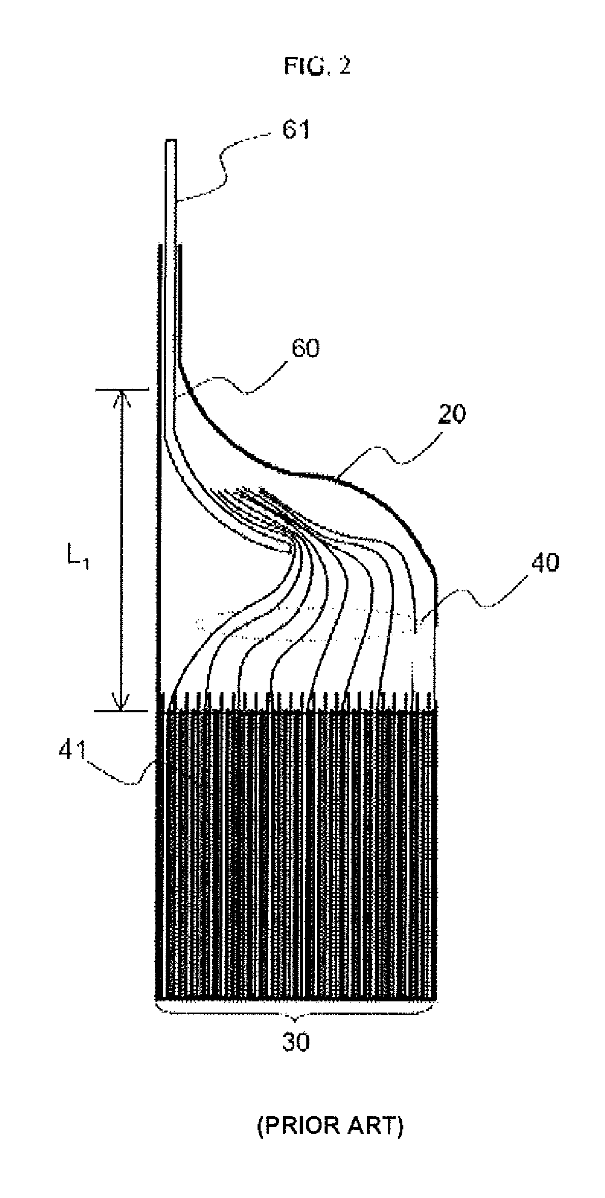
In addition, if gas is generated in the battery pack, the generated gas can easily remain in the dead space.
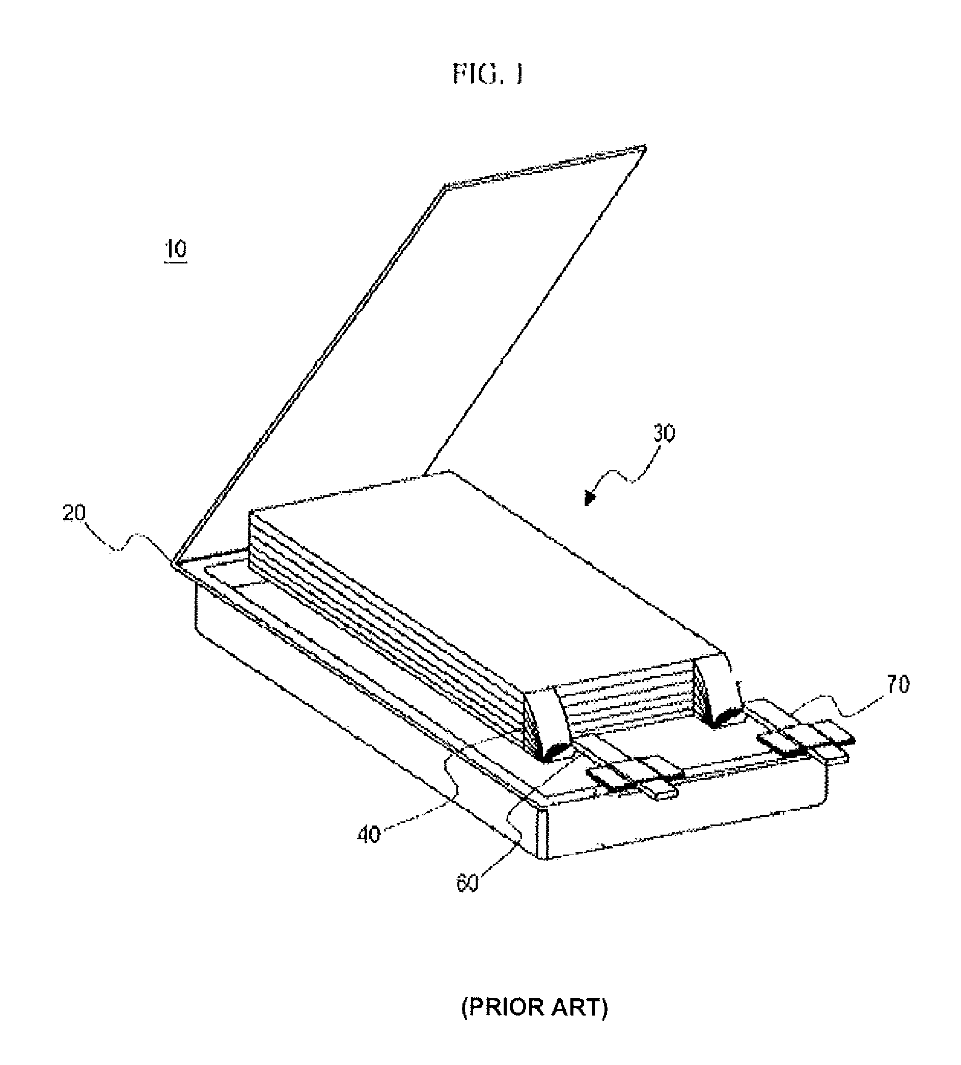
The conventional pouch type secondary battery is inefficient since many dead spaces are generated in the battery due to its structure and, even when external pressure applied to the secondary battery is increased to restrain generation of gas, it is difficult to restrain the generation of gas because a space where gas can remain exists inside the battery.

Method used


Image

  • Pouch type case and battery pack including the same
  • Pouch type case and battery pack including the same
  • Pouch type case and battery pack including the same

Examples


Embodiment Construction

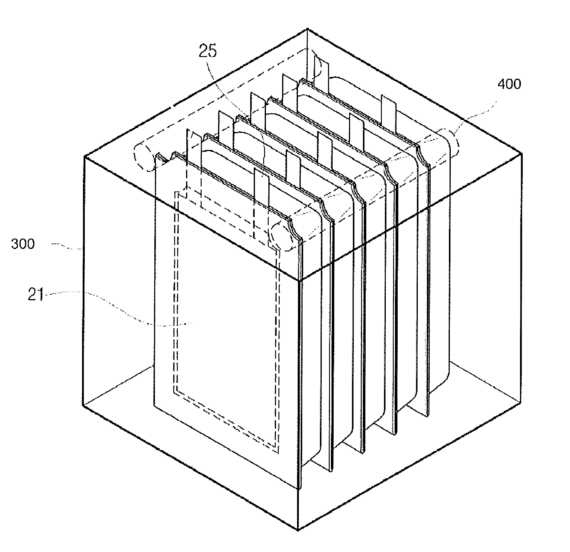
[0055]A pouch type case according to an embodiment of the present invention includes a space accommodating an electrode assembly composed of a positive plate, a negative plate and a separator interposed between the positive and negative plates and a sealing part sealing up an upper case and a lower case, in which a portion of the space and the sealing part, which corresponds to at least one of left and right sides of an electrode lead projected to the outside of the case, is trimmed to be indented toward the electrode assembly so as to minimize an internal dead space of a battery using the pouch type case.

[0056]As described above, the dead space in the electrode assembly is generated in a region where an electrode lead is formed in order to form a welded portion of electrode taps and the electrode lead.

[0057]Accordingly, to minimize the dead space, portions of the pouch type case according to the present invention other than a portion corresponding to a minimum region for forming th...


PUM

PropertyMeasurementUnit
voltageaaaaaaaaaa
lengthaaaaaaaaaa
widthaaaaaaaaaa

Abstract

The present invention relates to a pouch type case having trimming portions formed on both sides or four corners thereof and a battery pack including the same. The trimming portions are formed on the corners of the pouch type case such that the trimming portions are indented toward an electrode assembly accommodating part to reduce a unit area so as to increase pressure applied to unit cells when a battery pack is assembled, thereby facilitating assembling of the battery pack and increasing cell capacity per unit area. Furthermore, the unit cells can be fixed in the battery pack more stably. The pouch type case reduces the unit area so as to include a relatively large number of cells for pressure applied to the cells when the battery pack is assembled to thereby increase the cell capacity.

Description

CROSS-REFERENCE TO RELATED APPLICATIONS[0001]This application is a continuation of International Application No. PCT / KR2011 / 001927 filed on Mar. 21, 2011, which claims priority from Korean Patent Application No. 10-2010-0024879 filed in Republic of Korea on Mar. 19, 2010, the entire contents of which are incorporated herein by reference.TECHNICAL FIELD[0002]The present invention relates to a pouch type case and a battery pack including the same.BACKGROUND OF THE INVENTION[0003]With the development of portable electrode devices such as cellular phones, notebook computers, and camcorders, studies on rechargeable secondary batteries are actively performed. Particularly, the lithium secondary battery operating at a voltage of approximately 3.6V has capacity more than three times that of nickel-cadmium battery or nickel-metal hydride battery, which is widely used as a power supply of portable electronic devices, and high energy density per unit weight, and thus utilization and study of t...

Claims


Application Information

Patent Timeline
Patent Type & Authority Patents(United States)
IPC IPC(8): H01M2/02H01M2/10H01M50/469H01M50/548H01M50/55
CPCH01M2/0212H01M2/18H01M2/345H01M10/0413H01M10/045H01M10/0459H01M10/052H01M10/0583H01M10/0587H01M2/0456H01M2/12H01M2200/20Y02E60/122Y02T10/7011Y02E60/10H01M50/30H01M50/578Y02P70/50H01M50/469H01M50/55H01M50/548H01M50/105H01M50/178H01M50/557H01M50/211H01M50/186H01M2220/20H01M2220/10Y02T10/70
Inventor PARK, HYO SEOKSHIN, YOUNG JOONPARK, HYUN WOO
Owner LG ENERGY SOLUTION LTD
Learn More