Magnetic toner and image-forming method

a toner and magnetic technology, applied in the field of magnetic toner and image-forming method, can solve the problems of increasing the curvature of the bearing member or carrying member, reducing the amount of toner to be developed, and unable to obtain sufficient image density, etc., and achieve the effect of high density

Active Publication Date: 2013-04-23
CANON KK
View PDF17 Cites 34 Cited by
  • Summary
  • Abstract
  • Description
  • Claims
  • Application Information

AI Technical Summary

Benefits of technology

[0014]According to a preferred embodiment of the present invention, an image having the following characteristics can be obtained even when the toner of the present invention is combined with a toner carrying member having a small diameter: the image has a high density, causes no sweeping, and is vivid.

Problems solved by technology

However, the reduction in diameter of the latent image bearing member or toner carrying member means that the curvature of the bearing member or carrying member increases, and involves the emergence of the following detrimental effect: a developing zone becomes extremely narrow in a developing portion.
Particularly in jumping development as magnetic, one-component development, a narrow developing zone causes the following problem: the amount of toner to be developed reduces, so a sufficient image density cannot be obtained.
However, when a toner carrying member having a small diameter is used, the following problem is apt to arise: the insertion of the plate-like member into the developing zone additionally narrows the developing zone, with the result that an image to be formed hardly shows a high density.

Method used


Image

  • Magnetic toner and image-forming method
  • Magnetic toner and image-forming method
  • Magnetic toner and image-forming method

Examples


example 1

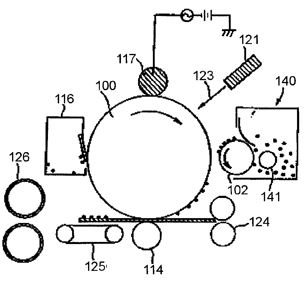
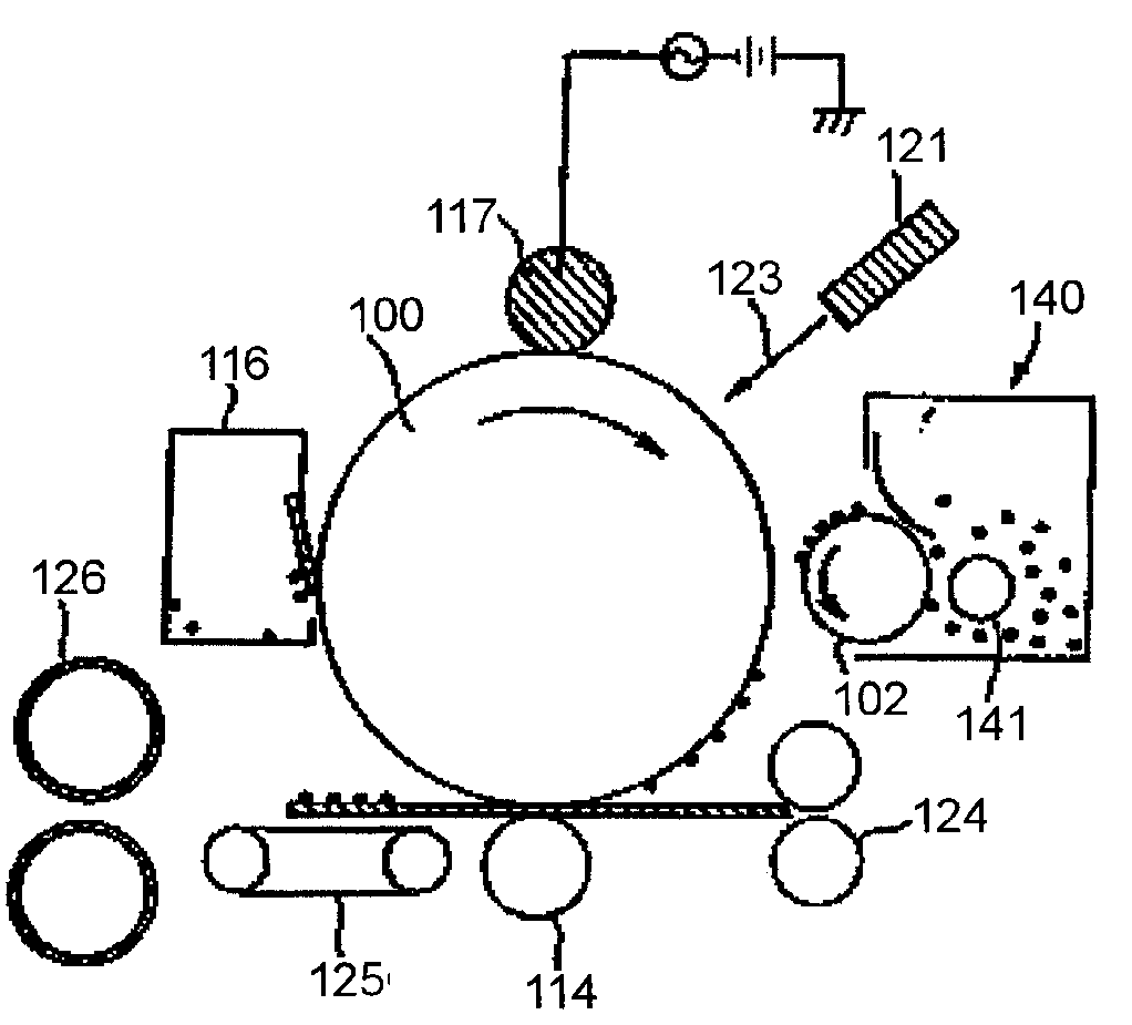
[0221]An LBP3000 (manufactured by Canon Inc.) was used as an image-forming apparatus, and a cartridge of the apparatus was reconstructed so as to be capable of storing the above toner carrying member 1.

[0222]A 2,000-sheet image output durability test was performed under a normal-temperature, normal-humidity environment (23° C. / 60% RH) by printing horizontal lines each having a print percentage of 3% according to a continuous mode with Toner 1 and the toner carrying member 1 while setting the free length of a toner control blade to 0.7 mm. Evaluation was performed before and after the durability test. It should be noted that A4 paper having a basis weight of 75 g / m2 was used as a recording medium. As a result, the acquisition of images each causing neither sweeping nor fogging to a non-image portion and each having a high density before and after the durability test was attained. Table 3 shows the results of the evaluation.

[0223]It should be noted that a method for evaluation for eac...

examples 2 to 7

[0231]An image output test was performed in the same manner as in Example 1 except that Toner 2, 3, 5, 6, 7, or 11 was used. As a result, each toner provided images at such a level that no problems in practical use arose or higher before and after the durability test. Table 3 shows a combination of a toner and a toner carrying member, and the results of the evaluation.

examples 8 to 12

[0234]An image output test was performed in the same manner as in Example 1 except that each of the toner carrying members 2 to 6 was used. As a result, each toner provided images at such a level that no problems in practical use arose or higher before and after the durability test. Table 4 shows a combination of a toner and a toner carrying member, and the results of the evaluation.


PUM


Abstract

To solve a thin image density and sweeping occurring when a toner carrying member having a small diameter is used, provided is an image-forming method including: a charging step; an electrostatic latent image-forming step; a developing step; a transferring step; and a fixing step, in which a magnetic toner to be used in the method has a specific weight average particle diameter (D4); the magnetic toner has a specific intensity of magnetization in a specific magnetic field; and a surface free energy of a surface of the magnetic toner and a surface free energy of a surface of a toner carrying member to be used in the method satisfy specific relationships.

Description

BACKGROUND OF THE INVENTION[0001]1. Field of the Invention[0002]The present invention relates to a toner to be used in a recording method utilizing an electrophotographic method or the like, and an image-forming method.[0003]2. Description of the Related Art[0004]Various electrophotographic methods have been known. A general electrophotographic method involves the utilization of a photoconductive substance, and includes: forming an electrostatic latent image on an electrostatic image bearing member (which may hereinafter be referred to as “photosensitive member”) by various means; developing the latent image with toner to provide a visible image; transferring the toner image onto a recording medium such as paper as required; and fixing the toner image on the recording medium with heat, pressure, or the like to provide a copied article. An image-forming apparatus which adopts such electrophotographic method is, for example, a copying machine or a printer. In recent years, such printe...

Claims


Application Information

Patent Timeline
Patent Type & Authority Patents(United States)
IPC IPC(8): G03G13/04
CPCG03G9/0819G03G9/0833G03G9/0834G03G9/0835G03G9/0836G03G9/0837G03G9/09716G03G9/09725G03G15/0914G03G2215/0614
Inventor MAGOME, MICHIHISADOJO, TADASHIYANASE, ERIKOMATSUI, TAKASHISANO, TOMOHISAHIROKO, SHUICHI
Owner CANON KK
Why Eureka
Try Eureka