

Digital control of PWM converters with nonlinear gain scheduling
a digital control and nonlinear gain technology, applied in the field of digital control of pwm converters with nonlinear gain scheduling, can solve problems such as stability problems
- Summary
- Abstract
- Description
- Claims
- Application Information
AI Technical Summary
Benefits of technology
Problems solved by technology
Method used
Image

Examples
Embodiment Construction
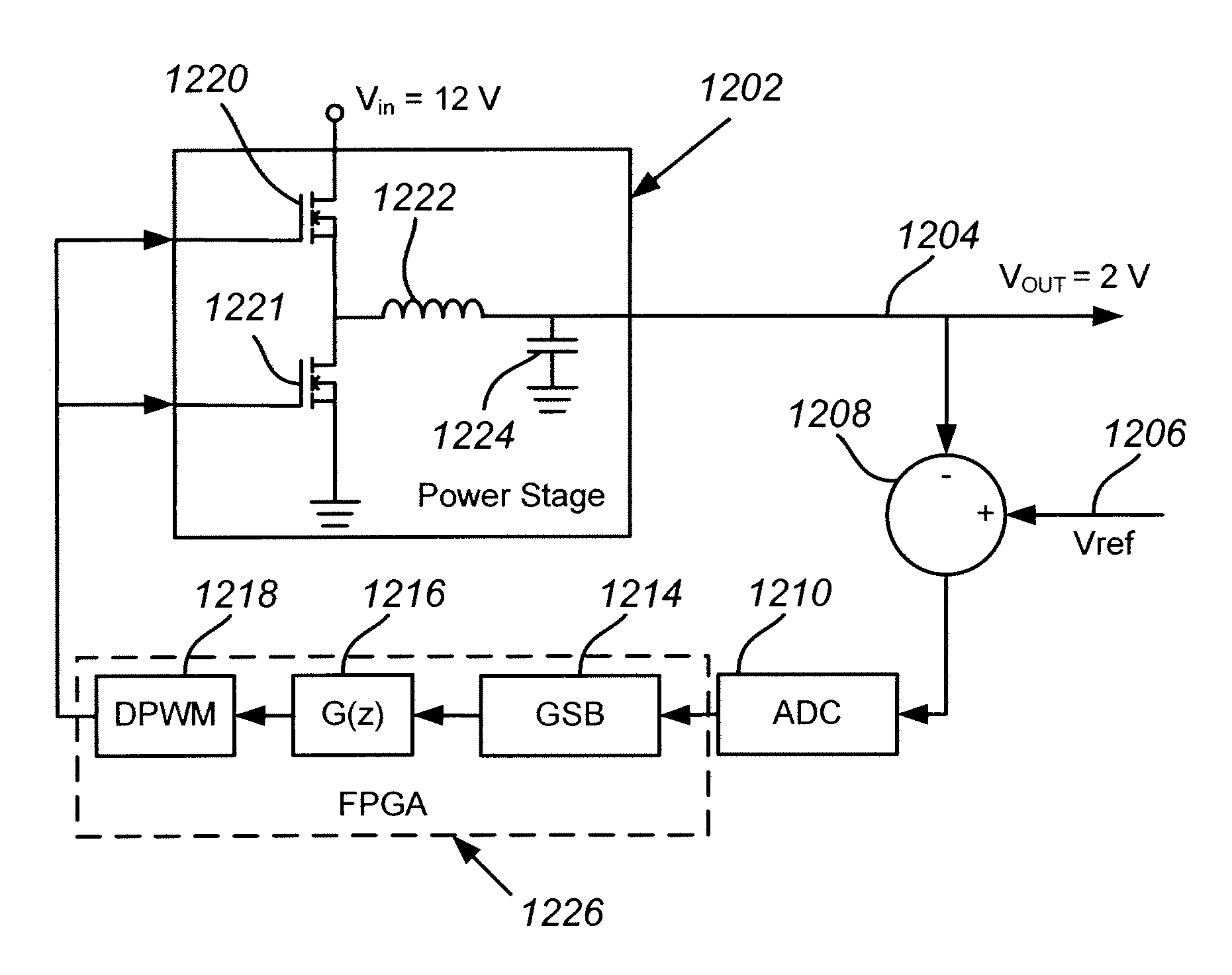
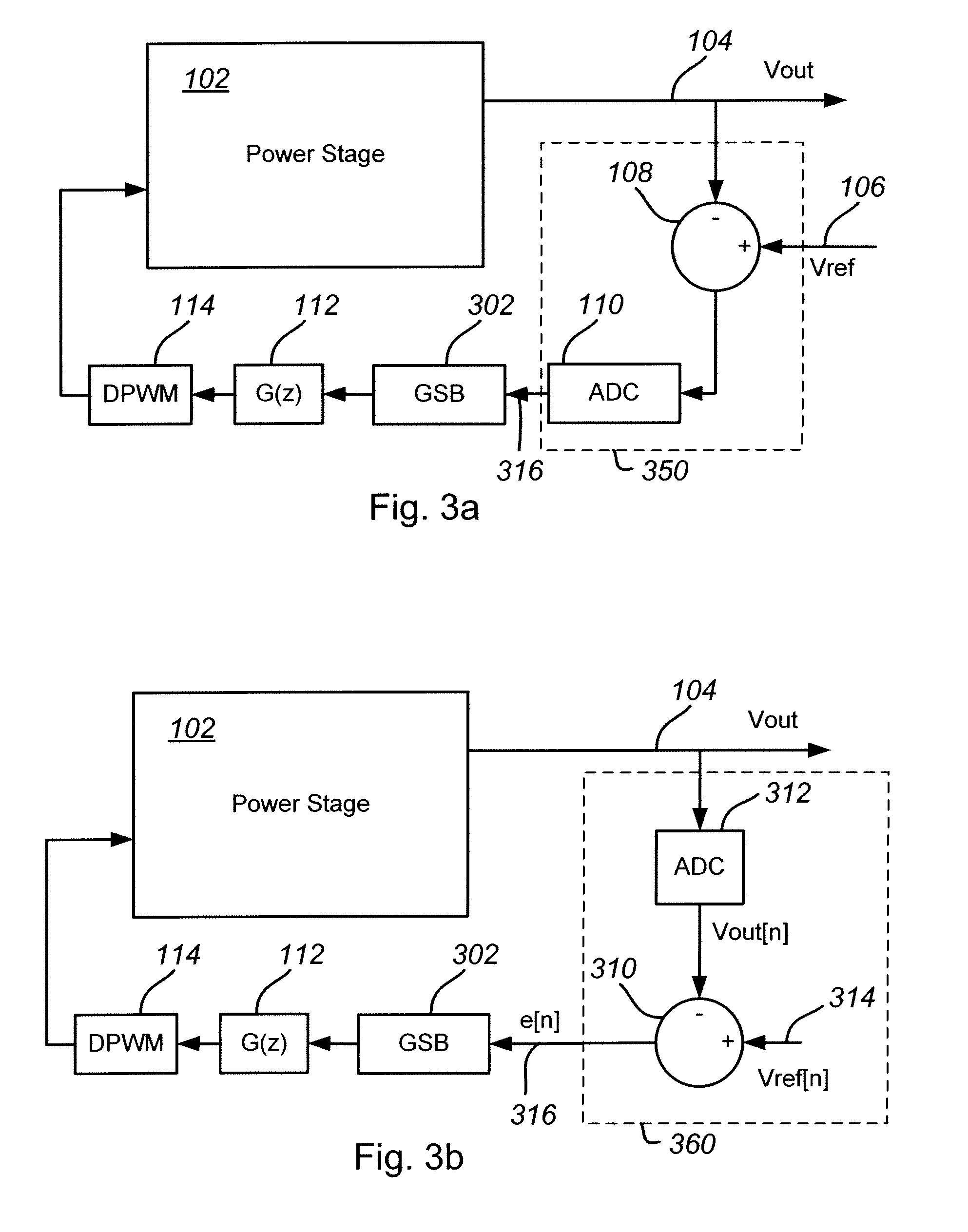
[0029]An embodiment of a digital PWM control system in accordance with the present invention is illustrated in FIG. 3a and introduces a non-linear gain scheduling block (GSB) 302 into the control loop. The output 104 of the power stage 102 is fed into an error comparison circuit 108 that calculates an error signal based on the difference between the power stage output 104 and a reference voltage 106. The error signal is digitized by an ADC 110 to create a digital error signal 316. The combination of the error comparison signal 108 and the ADC 110 is identified as the error sampling block 350. The digital error signal 316 is then fed to a gain scheduling block 302 that applies a non-linear input-to-output characteristic, described in further detail below, to the digitized error signal. The processed error signal is then fed through a compensator filter 112, which may have a standard PID character, that in turn drives a digital PWM controller 114 that controls the switching of the pow...
PUM
 Abstract
Description
Claims
Application Information