System and method for quantifying the presence of components in the exhaust of commercial and/or heavy-duty vehicles

a technology for commercial and/or heavy-duty vehicles, applied in the field of extractive sampling systems and quantification of can solve the problems of not accurately quantifying the presence of components in the exhaust of commercial and/or other heavy-duty vehicles, and the measurement acquired often does not represent emissions, etc., to achieve suppressed inaccuracy and/or enhanced accuracy. the effect of precision

Inactive Publication Date: 2013-04-30
ENVIROTEST SYST HLDG CORP
View PDF67 Cites 12 Cited by
  • Summary
  • Abstract
  • Description
  • Claims
  • Application Information

AI Technical Summary

Benefits of technology

[0012]In certain implementations, the gathering structure may be disposed at or near the roadway, and may have at least one surface that causes exhaust emitted by the vehicle at an elevated level (e.g., from a stack exhaust system) to gather around the collector. The roadway may be an actual road lane, and / or may be a separate test lane. In some implementations, the gathering structure may include a roof that spans the path of the vehicle in the roadway, and the collector may be disposed such that the collector openings are located at or near an underside surface of the roof. In such implementations, exhaust ejected by the vehicle may be gathered and pooled around the collector openings by the underside surface of the roof, which may facilitate the reception of the exhaust into the collector openings. In some instances, the gathering structure may be impermeable to one or both of water and / or exhaust gases. In these instances, the gathering structure may further provide shelter for the collector openings and / or emitted exhaust from precipitation. Since the introduction of precipitation into the collector openings may interfere with the operation of the collector, the component detection system, and / or the flow generator generating the flow of air from the collector openings to the component detection system, the provision of shelter by the gathering structure may further enhance the collection and analysis of exhaust emitted by the vehicle at an elevated level.
[0015]In some implementations, the collector includes a plurality of collector openings that are arranged above the surface of a roadway along which the vehicle is traveling so as to receive the emissions of the vehicle, which are emitted at an elevated level (e.g., from high-stacks). For example, the collector may include a perforated pipe that forms the openings. In certain implementations, the collector may be disposed such that the collector openings are arranged along a path from between a first location and a second location that corresponds to the path of the vehicle between the first location and the second location. For example, the collector openings may be disposed in an array above the path of the vehicle between the first location and the second location to receive exhaust emitted upwards by the vehicle. This may facilitate the collection of exhaust by the collector openings, as exhaust emitted from the vehicle will be directed by momentum, turbulence, and / or other phenomena to the collector openings as the vehicle travels along the roadway.
[0018]In various implementations, the collector may be configured such that collection times for exhaust emissions emitted by the vehicle to be conveyed through the collector to the component detection system vary as a function of position along the roadway. Collection times may be longer for locations that are closer to a first location, and shorter for locations that are closer to a second location. Since exhaust emissions are emitted first at the first location and then on toward the section location (e.g., as the vehicle proceeds along the roadway), the differences in collection times may cause exhaust emissions collected along the roadway to be aggregated into an integrated body of exhaust that is conveyed by the collector to the component detection system. To provide collection times that will result in exhaust emission aggregation, the size and / or shape of collector openings, the size and / or shape of lumen cross-section, lumen length, flow generator parameters, and / or other factors may be adjusted or configured. One or more of these factors may be controlled dynamically (e.g., based on vehicle speed) to ensure aggregation of the exhaust emissions. Aggregation of the exhaust emissions may increase the concentrations of the exhaust emissions, which may enhance the precision and / or accuracy of the analysis performed by the component detection systems.
[0021]The system and method of the invention as disclosed herein may be utilized to quantify the presence of one or more components in a plurality of samples of exhaust taken according to a predetermined sampling rate. In some instances, the quantification of the one or more components in the exhaust for the plurality of samples may be aggregated in order to provide an aggregated quantification of the one or more components in the exhaust emitted by the vehicle. The aggregated quantification may provide an enhanced accuracy and / or precision in determining the quantity and / or nature of the emissions of the vehicle. For example, even if the vehicle is being operated in some atypical fashion (e.g., changing gears) along the pathway, the aggregation of the quantification may suppress inaccuracies caused by this momentary atypical operation. In some instances, the aggregated quantification may be determined by averaging the quantifications of the presence of the one or more components in the plurality of exhaust samples.

Problems solved by technology

One drawback associated with dynamometer testing, however, is that the measurements acquired often do not represent emissions under actual operating conditions when automobiles are in motion on a roadway or other driving surface.
However, existing systems configured to remotely test emissions tend to focus on passenger cars with exhaust systems that emit exhaust relatively close to the ground.
As a result, remote emissions sensing systems designed to detect emissions for low-emitting vehicles (e.g., typical passenger automobiles) may not accurately quantify the presence of components in the exhaust of commercial and / or other heavy-duty vehicles that emit exhaust at an elevated position (or level).
Known remote emissions sensing systems, however, do not appear to make real-time “on-the-fly” determinations as to whether a moving vehicle to be tested (under actual operating conditions) is emitting exhaust at an elevated position (or level) or at a lower position at or near ground-level in order to be able to sample exhaust emissions accordingly.
Measurements taken during a brief period of atypical operation may inaccurately indicate elevated levels of emission by the vehicle.
These and other problems can reduce the benefits of short duration (e.g., typically a second or less) remote emissions sensing systems.

Method used


Image

  • System and method for quantifying the presence of components in the exhaust of commercial and/or heavy-duty vehicles
  • System and method for quantifying the presence of components in the exhaust of commercial and/or heavy-duty vehicles
  • System and method for quantifying the presence of components in the exhaust of commercial and/or heavy-duty vehicles

Examples


Embodiment Construction

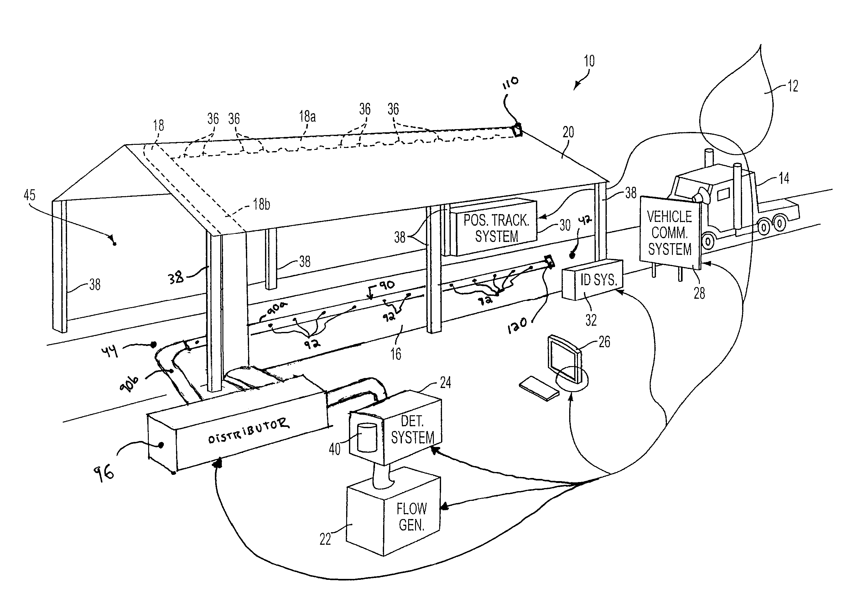
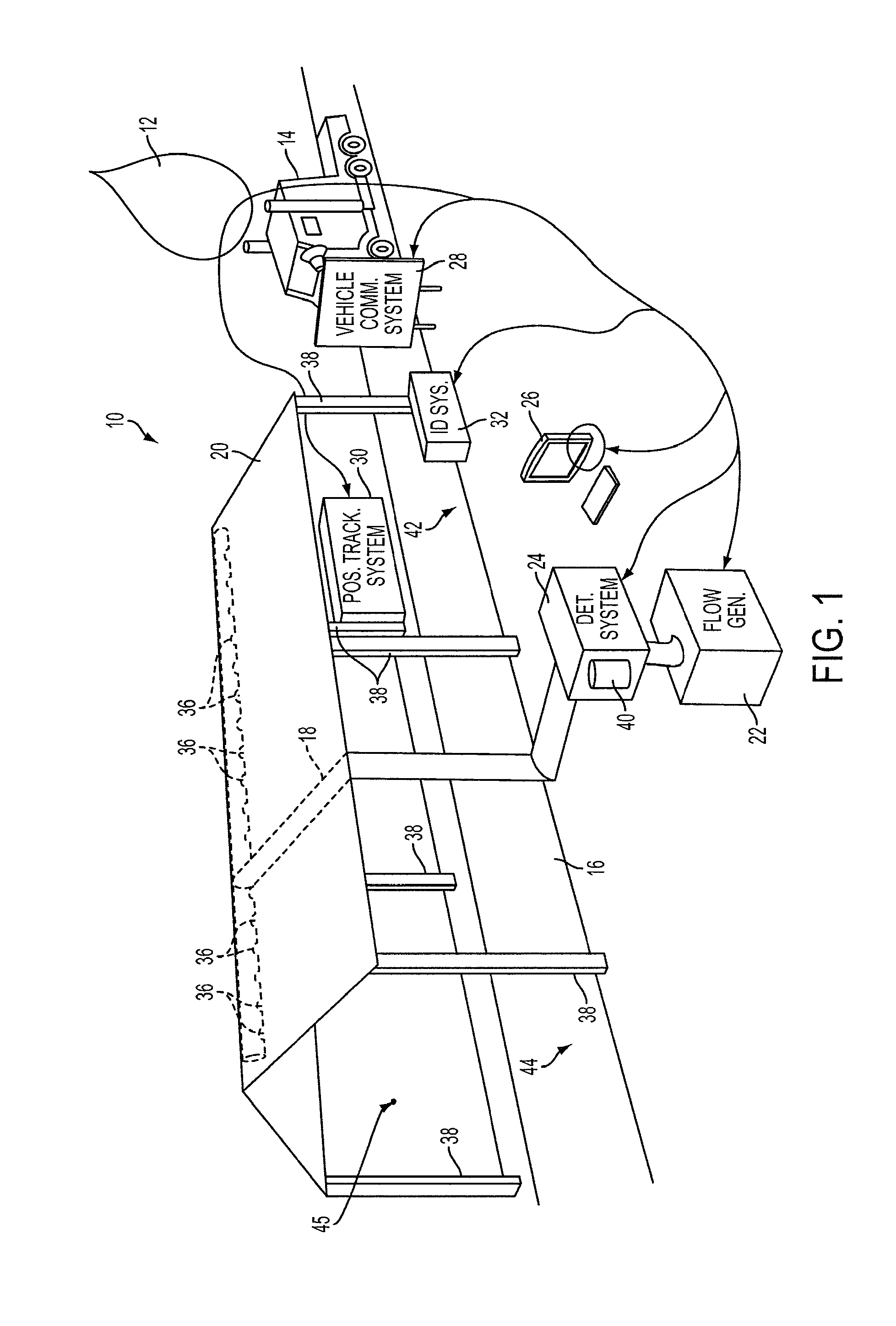
[0035]FIG. 1 illustrates a system 10 for analyzing an exhaust plume 12 of a vehicle 14 traveling on a roadway 16 under actual operating conditions, in accordance with one or more implementations of the invention. It should be appreciated that exhaust leaving the exhaust pipe(s) of moving vehicle 14 (e.g., via exhaust “stacks” of a semi-trailer or bus) is entrained in the vehicle's turbulent wake and continues to dissipate as vehicle 14 travels away. Despite the present turbulence, the dissipation of the exhaust will have a directionality associated with one or both of the location at which the exhaust is emitted and / or the direction in which it is propelled by momentum upon being emitted. For example, some commercial and / or heavy-duty vehicles generally emit exhaust at an elevated position and / or propel emitted exhaust either upwards or to the side. As a result, remote emissions sensing systems designed to detect emissions for low-emitting vehicles (e.g., typical passenger automobil...


PUM

PropertyMeasurementUnit
pressureaaaaaaaaaa
lengthaaaaaaaaaa
timeaaaaaaaaaa

Abstract

A system and / or method for quantifying the presence of one or more components in vehicle exhaust, and more particularly to a non-contact, sampling system and method for quantifying the presence of one or more components in exhaust emissions of commercial and / or heavy-duty vehicles that emit exhaust at an elevated level, under actual operating conditions.

Description

CROSS-REFERENCE TO RELATED APPLICATIONS[0001]This Application is a continuation-in-part of U.S. patent application Ser. No. 13 / 153,151, filed Jun. 3, 2011 (which issued as U.S. Pat. No. 8,347,701 on Jan. 8, 2013), which is a continuation-in-part of U.S. patent application Ser. No. 13 / 052,815, filed Mar. 21, 2011 (which issued as U.S. Pat. No. 8,266,952 on Sep. 24, 2012), which is a continuation of U.S. patent application Ser. No. 12 / 114,189, filed May 2, 2008 (which issued as U.S. Pat. No. 7,930,931 on Apr. 26, 2011), each of which are hereby incorporated by reference herein in their entirety.FIELD OF THE INVENTION[0002]The invention relates generally to the quantification of the presence of one or more components in vehicle exhaust, and more particularly to a non-contact, extractive sampling system and method for quantifying the presence of one or more components in exhaust emissions of commercial and / or heavy-duty vehicles that emit exhaust at an elevated position (or level) and / o...

Claims


Application Information

Patent Timeline
Patent Type & Authority Patents(United States)
IPC IPC(8): G01N33/00
CPCG01M15/108G01N1/2252G01N15/06G01M15/102G01N1/26G01N15/0656G01N21/3504G01N2015/0693G01N15/065
Inventor STEDMAN, DONALD H.
Owner ENVIROTEST SYST HLDG CORP
Why Eureka
Try Eureka