
Tool, tool body and cutting head

a technology of cutting head and tool body, which is applied in the direction of boring/drilling equipment, turning equipment, milling equipment, etc., can solve the problems of high tolerance requirements for these surfaces and relatively complicated to achieve by mechanical machining, and achieve the effect of facilitating the formation of tool body, and facilitating the formation of cutting head

Active Publication Date: 2013-04-30
SECO TOOLS AB
View PDF15 Cites 19 Cited by
  • Summary
  • Abstract
  • Description
  • Claims
  • Application Information

AI Technical Summary

Benefits of technology

The invention relates to a tool used in drilling bores in a bore drilled by the tool. The tool has a cylindrical cutting head that is attached to a tool body. The gripping surfaces of the tool body and the cutting head prevent the cutting head from being displaced in axial direction away from the tool body when the tool is pulled out of the bore. This prevents the cutting head from sliding in axial direction away from the tool body and ensures that the cutting head follows the tool body when the tool body is pulled out. The gripping surfaces are cylindrical and parallel with the centre axis of the tool body and the cutting head, making it easier to achieve by mechanical machining. The tool body and the cutting head can have simplified shapes, and the gripping surfaces can be easily machined. The tool body and the cutting head can have stop surfaces that are parallel with the centre axis of the tool body and the cutting head, respectively, which makes it easier to achieve by mechanical machining. The coupling portion of the tool body and the cutting head can have a compact design with a short extension in axial direction.

Problems solved by technology

A disadvantage with these conical gripping surfaces is that the tolerance requirements are high for these surfaces and that they are relatively complicated to achieve by means of mechanical machining.

Method used


Image

  • Tool, tool body and cutting head
  • Tool, tool body and cutting head
  • Tool, tool body and cutting head

Examples


Embodiment Construction

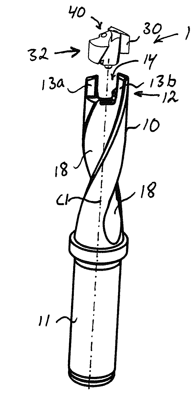
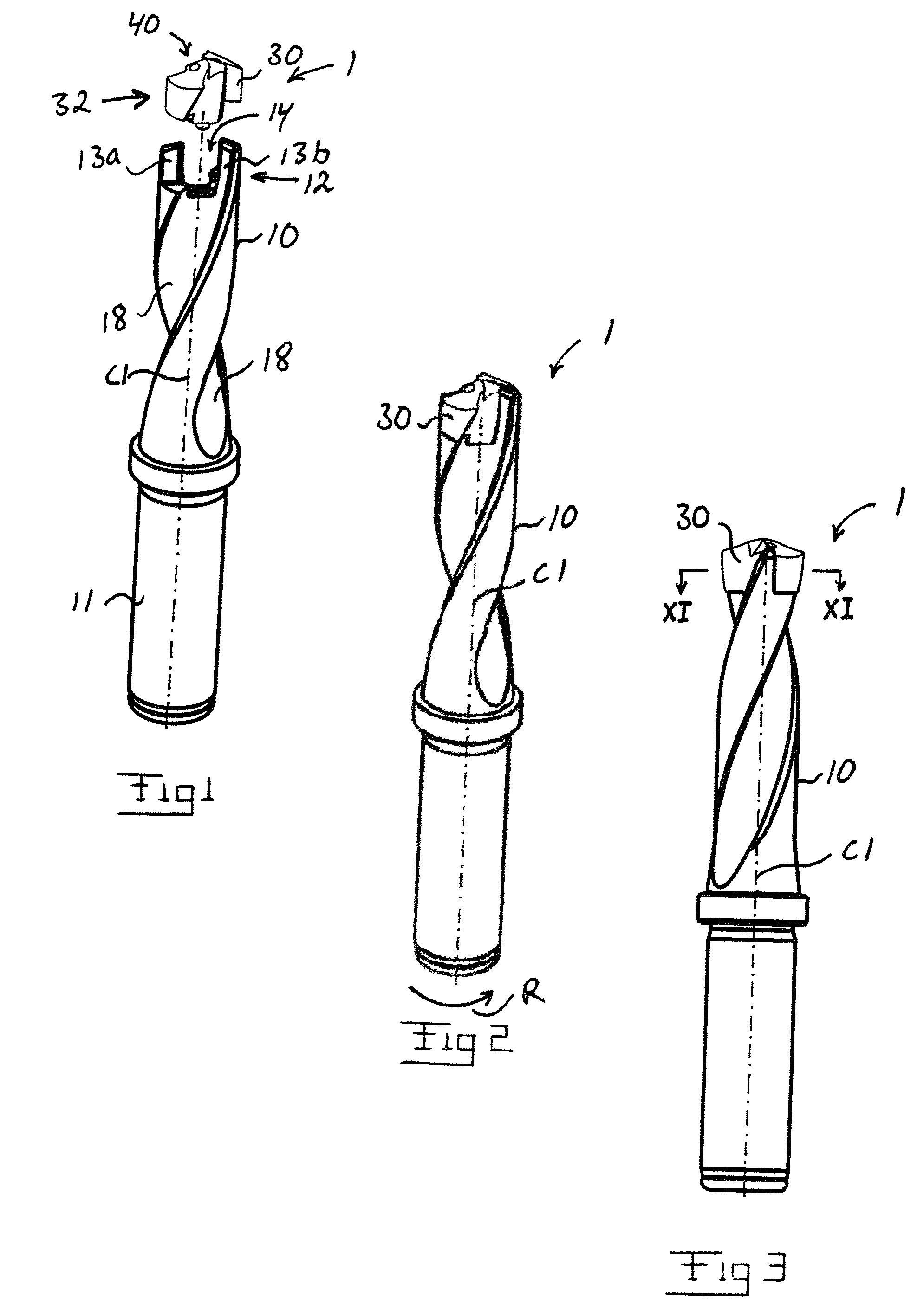
[0023]The tool 1 of the invention is intended to be rotated for cutting machining of a workpiece. In the illustrated example, the tool is designed as a twist drill, but the tool of the invention could also be designed as another type of tool for rotary cutting machining, such as for instance a milling cutter or the similar.

[0024]The intended direction of rotation of the tool 1 for machining is marked with the arrow R in FIGS. 2, 4 and 11-12. This direction of rotation is in the following denominated “machining direction of rotation” and consequently constitutes the direction in which the tool is intended to be rotated in order to achieve cutting machining of a, preferably metallic, workpiece. Alternatively, the workpiece can be rotated while the tool is kept stationary.

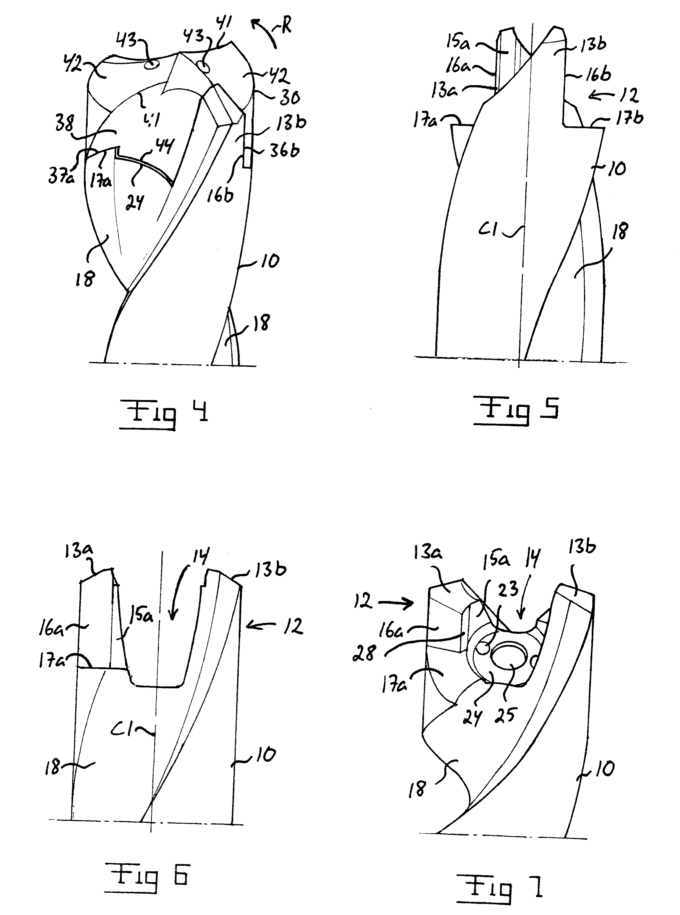
[0025]The tool 1 comprises a tool body 10 and a replaceable cutting head 30, which is detachably attachable to the tool body.

[0026]The cutting head 30 is formed in a one piece of a suitable cemented carbide, i.e. made...


PUM

PropertyMeasurementUnit
angleaaaaaaaaaa
torqueaaaaaaaaaa
radiusaaaaaaaaaa

Abstract

A tool for rotary cutting machining includes a tool body and a replaceable cutting head detachably attachable to the tool body. The cutting head has a coupling portion which is receivable in a space between two axially projecting coupling legs of the tool body. Cylindrical internal gripping surfaces are arranged in said space and designed for engagement with corresponding cylindrical external gripping surfaces of the cutting head. The gripping surfaces of the cutting head and the gripping surfaces of the tool body are dimensioned so as to prevent, by engagement with each other, the cutting head from being displaced in axial direction away from the tool body when the cutting head is attached to the tool body. A tool body and a cutting head included in such a tool are also disclosed.

Description

BACKGROUND AND SUMMARY[0001]The present invention relates to a tool for rotary cutting machining with a tool body and a replaceable cutting head detachably attachable to the tool body. The invention also relates to a tool body and a cutting head included in such a tool.[0002]U.S. Pat. No. 5,988,953 A and U.S. Pat. No. 5,971,673 A disclose a known tool, wherein the mutual gripping surfaces of the tool body and the cutting head are conical and widen in the direction towards the rear end of the tool body and the cutting head, respectively, so as to thereby achieve a positive locking in axial direction between the tool body and the cutting head. This positive locking prevents the cutting head from being displaced in axial direction away from the tool body, for instance when the tool is pulled out of a bore drilled by means of the tool. A disadvantage with these conical gripping surfaces is that the tolerance requirements are high for these surfaces and that they are relatively complicat...

Claims


Application Information

Patent Timeline
Patent Type & Authority Patents(United States)
IPC IPC(8): B23B51/02
CPCB23B51/02B23C5/10B23B2205/02B23B2250/12B23B2251/02Y10T408/95Y10T408/892Y10T408/9098Y10T408/9097Y10T408/907B23C2210/03B23B2240/32B23C5/20B23C2210/40B23C2222/28B23C2226/315B23C2250/12B23C5/22
Inventor FREJD, STEFAN
Owner SECO TOOLS AB
Learn More