Layered reactive particles with controlled geometries, energies, and reactivities, and methods for making the same

a reactive particle and geometries technology, applied in the field of energetic systems, can solve the problems of surface contamination, large particle agglomeration, non-uniform distribution of reactants and densities, etc., and achieve the effects of reducing bi-layer thickness, easy tuning, and increasing reaction speed and sensitivity of materials

Active Publication Date: 2013-04-30
LAWRENCE LIVERMORE NAT SECURITY LLC +1
View PDF7 Cites 2 Cited by
  • Summary
  • Abstract
  • Description
  • Claims
  • Application Information

AI Technical Summary

Benefits of technology

[0014]Generally, the present invention is an energetic composite comprising a plurality of reactive particles each having a reactive multilayer construction with alternating reactant layers for controlling energies and reactivities, and formed as a cylindrically-curved body (or otherwise rod-contoured body) whose geometry may be easily tailored / controlled (as a part of a fabricating step) so as to enable easy handling and low packing fractions, and thus deliver improved performance in a variety of energetic applications. The present invention also includes methods for fabricating these layered reactive particles of the energetic composite to have specific, controlled external geometries, controlled internal geometries and properties, and a controlled reactive multilayer construction. For example, the reactive particles may be specifically fabricated to have a preferred range of maximum external dimensions between about 1 micron and about 500 microns, a preferred range of packing fractions between about 1% and about 70%, a preferred range of reactant layer spacing from about 1 nm to about 1000 nm, a preferred range of heats of reaction (500 J / g to 4300) / g), and a preferred range of reactant layer spacing from about 1 nm to about 1000 nm.
[0017]The external geometries or volume of the reactive particles may be controlled and specified by selecting a predetermined length, width (or outer diameter), and thickness, which in turn may be used to control the packing fraction when the reactive particles are packed into a given space. Packing fraction or ratio is defined as the ratio of the total volume of a set of objects packed into a given space to the volume of that space, and is a function of the reactive particle's external geometry. In particular, by controlling the thickness and / or the inner radial distance between the innermost surface of the reactive multilayer and the longitudinal axis, one can easily tune the fraction of the particle's total volume that is occupied by reactive material, especially while holding the length and width fixed. Hence, the total packing fraction of the energetic material can be easily varied from about 1% to about 70%. And in another preferred embodiment, the respective lengths, widths, and thicknesses between the reactive particles may be made substantially uniform. In this manner, nearly identical geometries and volumes can lead to consistent particle-particle interactions and a controlled packing fraction.
[0018]The reactive particles of the energetic composite of the present invention are fabricated in a first exemplary method by first providing a rod-shaped substrate as described above, and successively depositing reactive layers on all sides of the rod-shaped substrate to form a reactive multilayer having a tube-shaped configuration. All sides of the rod-shaped substrate may be coated by first depositing on one side followed by coating on an opposite side. Alternatively, the tube-shaped configuration may be produced by rotating the substrate during deposition to evenly coat the substrate on all sides. The deposition step may continue until a desired or predetermined thickness is produced, one that in combination with a predetermined length and predetermined width will enable the reactive particles to be packed in a given space with a desired packing fraction from about 1% to about 70%.
[0019]The reactive multilayer construction of the reactive particles are comprised of preferably two materials (or more) of a type reactive with each other, in alternating layered arrangement to form a set of repeating bi-layers. And various depositions methods and strategies known in the art may be employed to fabricate the reactive multilayer construction of the reactive particles. For example, any of the energetic nanolaminate fabrication methods disclosed in the Barbee references (U.S. Pat. Nos. 5,538,795 and 5,547,715, U.S. Pat. Publication No. 2004 / 0060625) may be employed, and are incorporated by reference herein. In particular, the Barbee references teach the fabrication of energetic nanolaminates with tailored and precise reaction wave front velocities, energy release rates, and ignition temperatures. In any case, it is appreciated that the stored energy and reaction velocities of the energetic multilayers and nanolaminates can be systematically and independently controlled by materials selection, size scale of the layers, etc. For example, a monolithic energetic multilayer having reduced thicknesses of individual layers may be used to increase the reaction speed and sensitivity of the material. This is because with decreasing bi-layer thickness the average diffusion distance between reactant species in adjacent layers decreases. The bi-layer thicknesses of the foils can be readily and precisely controlled via magnetron sputtering. The bi-layer thickness of the multilayer structure of the monolithic multilayer and the energetic pieces is preferably from about 10 nm to about 200 nm.

Problems solved by technology

While more reactive, these powered particles have been known to suffer from surface contamination, agglomeration in larger particles, non-uniform distributions of reactants and densities in multi-powder compacts, variability in particle size, and chemical instability.
However, the resulting particles are typically not uniform in their geometry, which prevents their packing fraction and hence energy per volume from being easily controlled.
However, the resulting particles typically have only two to three shells or layers and thus are very small and very hard to manipulate if the reactant spacing (shell thickness) is only tens of nanometers thick.

Method used


Image

  • Layered reactive particles with controlled geometries, energies, and reactivities, and methods for making the same
  • Layered reactive particles with controlled geometries, energies, and reactivities, and methods for making the same
  • Layered reactive particles with controlled geometries, energies, and reactivities, and methods for making the same

Examples


Embodiment Construction

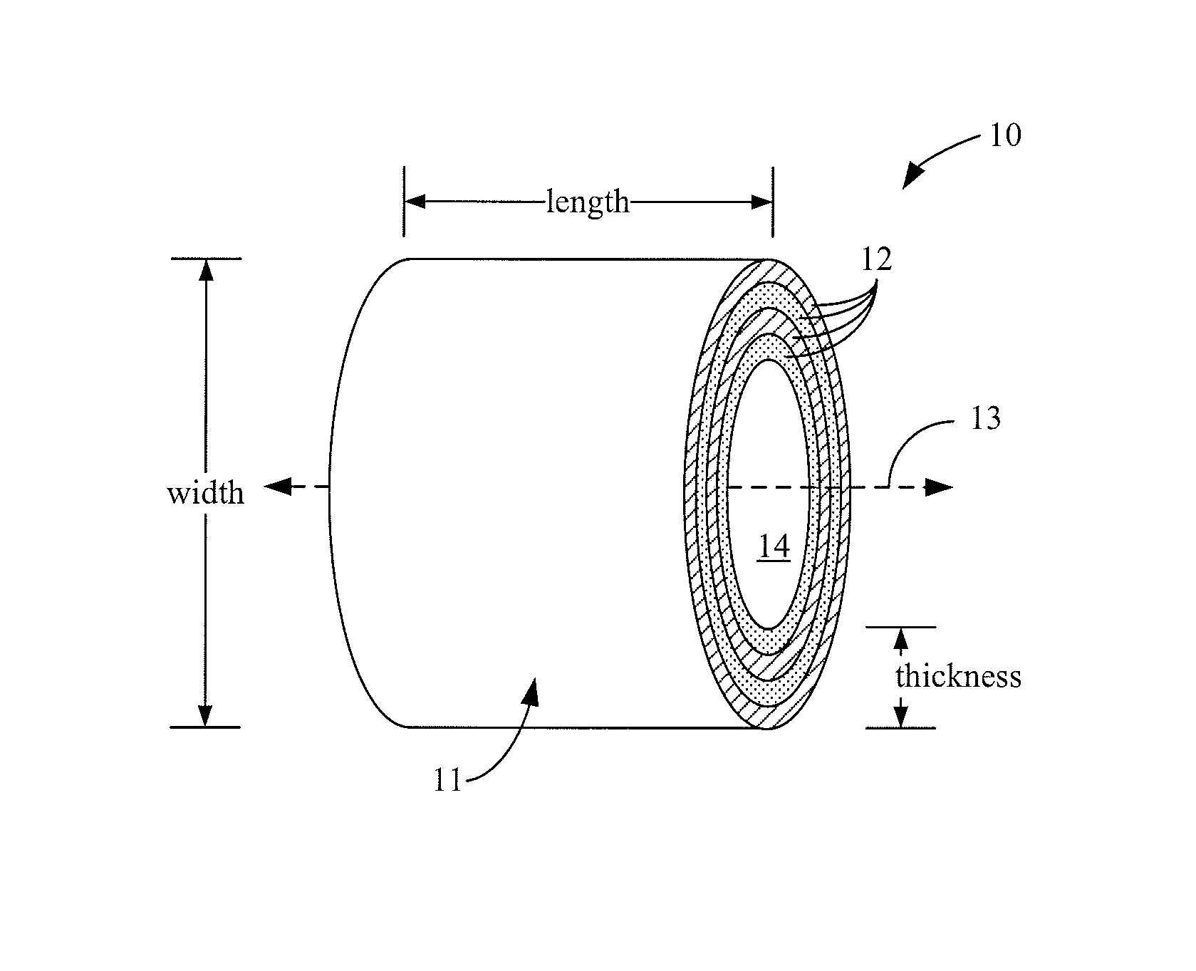
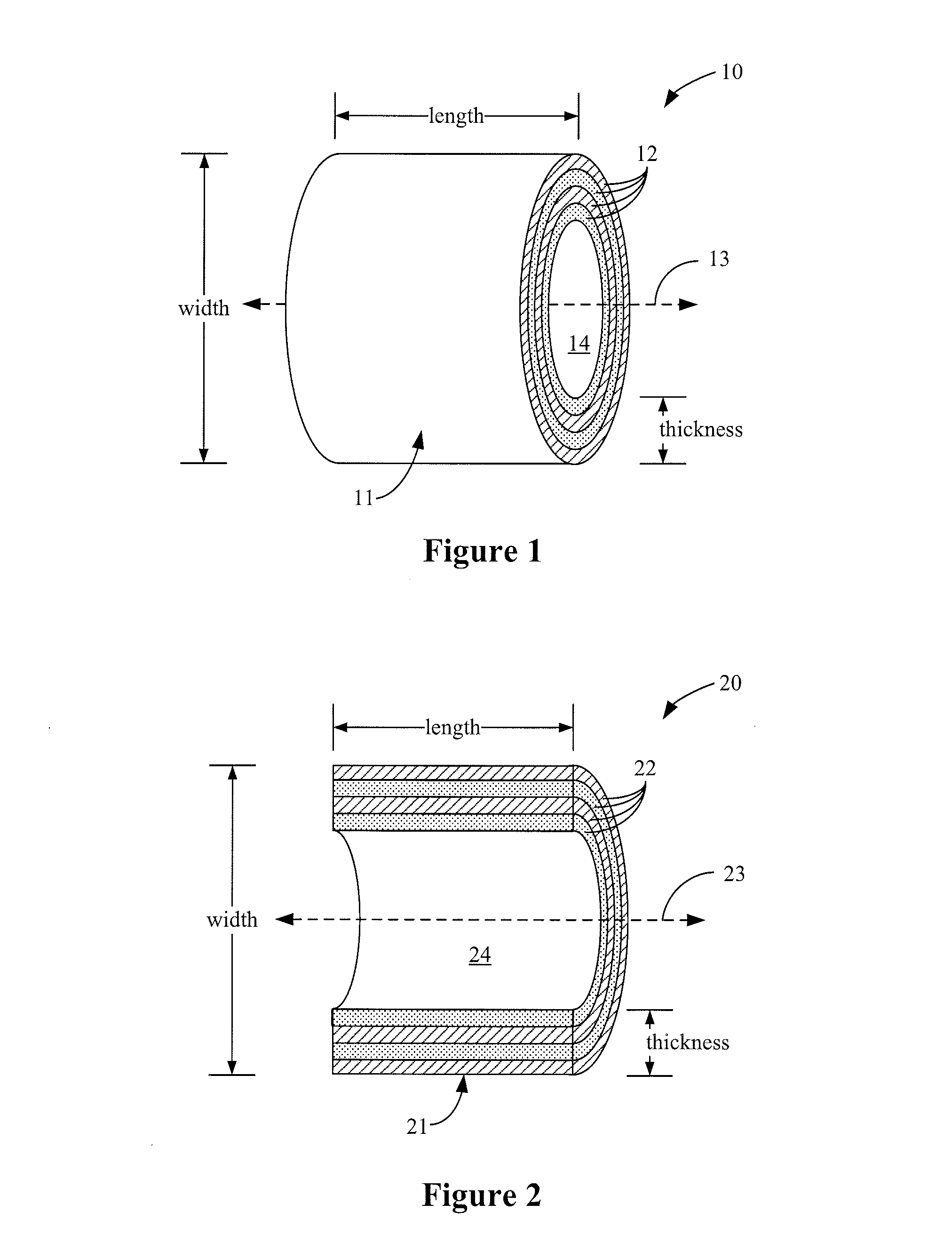
[0034]Turning now to the drawings, FIG. 1 shows a first exemplary embodiment of a single reactive particle, generally indicated at reference character 10, which represents one of a plurality of such particles which comprise the energetic composite of the present invention. As can be seen in FIG. 1, the reactive particle has a generally tube-shaped body 11 surrounding a hollow core 14, and radially spaced from a central cylindrical axis 13. The length of the particle is shown taken along the cylindrical axis 13, and the width of the particle is shown taken orthogonal to the cylindrical axis. The tube-shaped body 11 has a multilayer construction with multiple reactive layers 12 stacked in a radially outward direction from the axis. The thickness of the reactive particle is shown as the total thickness of all the multiple reactive layers combined.

[0035]And FIG. 2 shows a second exemplary embodiment of a single reactive particle, generally indicated at reference character 20, which repr...


PUM

PropertyMeasurementUnit
widthaaaaaaaaaa
widthaaaaaaaaaa
temperaturesaaaaaaaaaa

Abstract

An energetic composite having a plurality of reactive particles each having a reactive multilayer construction formed by successively depositing reactive layers on a rod-shaped substrate having a longitudinal axis, dividing the reactive-layer-deposited rod-shaped substrate into a plurality of substantially uniform longitudinal segments, and removing the rod-shaped substrate from the longitudinal segments, so that the reactive particles have a controlled, substantially uniform, cylindrically curved or otherwise rod-contoured geometry which facilitates handling and improves its packing fraction, while the reactant multilayer construction controls the stability, reactivity and energy density of the energetic composite.

Description

CLAIM OF PRIORITY IN PROVISIONAL APPLICATION[0001]This application claims priority in provisional application filed on Oct. 23, 2008, entitled “Layered Reactive Particles with Controlled Geometries, Energies, and Reactivities, and Methods for Making the Same” Ser. No. 61 / 107,915, by Alexander E. Gash et al, and incorporated by reference herein.FEDERALLY SPONSORED RESEARCH OR DEVELOPMENT[0002]The United States Government has rights in this invention pursuant to Contract No. DE-AC52-07NA27344 between the United States Department of Energy and Lawrence Livermore National Security, LLC for the operation of Lawrence Livermore National Laboratory.BACKGROUND OF THE INVENTION[0003]A. Technical Field[0004]The present invention relates to energetic systems such as primers, igniters, and detonators, and more particularly to an energetic composite and a method of fabricating the energetic composite comprising reactive particles having a multilayer construction formed by the deposition of reacti...

Claims


Application Information

Patent Timeline
Patent Type & Authority Patents(United States)
IPC IPC(8): A47G19/22
CPCB32B1/08B29C41/003C06B45/14C23C14/14C06B43/00C23C16/01C25D1/02C06B21/0083Y10T428/2975Y10T428/131Y10T428/25
Inventor FRITZ, GREGORY M.KNEPPER, ROBERT ALLENWEIHS, TIMOTHY P.GASH, ALEXANDER E.SZE, JOHN S.
Owner LAWRENCE LIVERMORE NAT SECURITY LLC
Why Eureka
Try Eureka