Supercharge Your Innovation With Domain-Expert AI Agents!

Tool path display apparatus with deceleration factor identification means for machine tool

a technology of deceleration factor and identification means, which is applied in the direction of electric programme control, program control, instruments, etc., can solve the problems of determining the condition under which the speed is restricted, the speed may be restricted, etc., and achieves the effect of easy determination

Active Publication Date: 2013-04-30
FANUC LTD
View PDF10 Cites 3 Cited by
  • Summary
  • Abstract
  • Description
  • Claims
  • Application Information

AI Technical Summary

Benefits of technology

The present invention provides a tool path display apparatus for a machine tool with a numerical controller that can easily determine the condition under which the speed of a tool center point is restricted at each point on a tool path while processing for restricting the speed is being performed under various conditions. This allows for better control and optimization of the machining process.

Problems solved by technology

However, the tool center point does not always move at the commanded speed, and the speed may be restricted under various conditions depending on the place.
It is difficult, however, to determine the condition under which the speed is restricted at each point on a tool path.

Method used


Image

  • Tool path display apparatus with deceleration factor identification means for machine tool
  • Tool path display apparatus with deceleration factor identification means for machine tool
  • Tool path display apparatus with deceleration factor identification means for machine tool

Examples


first embodiment

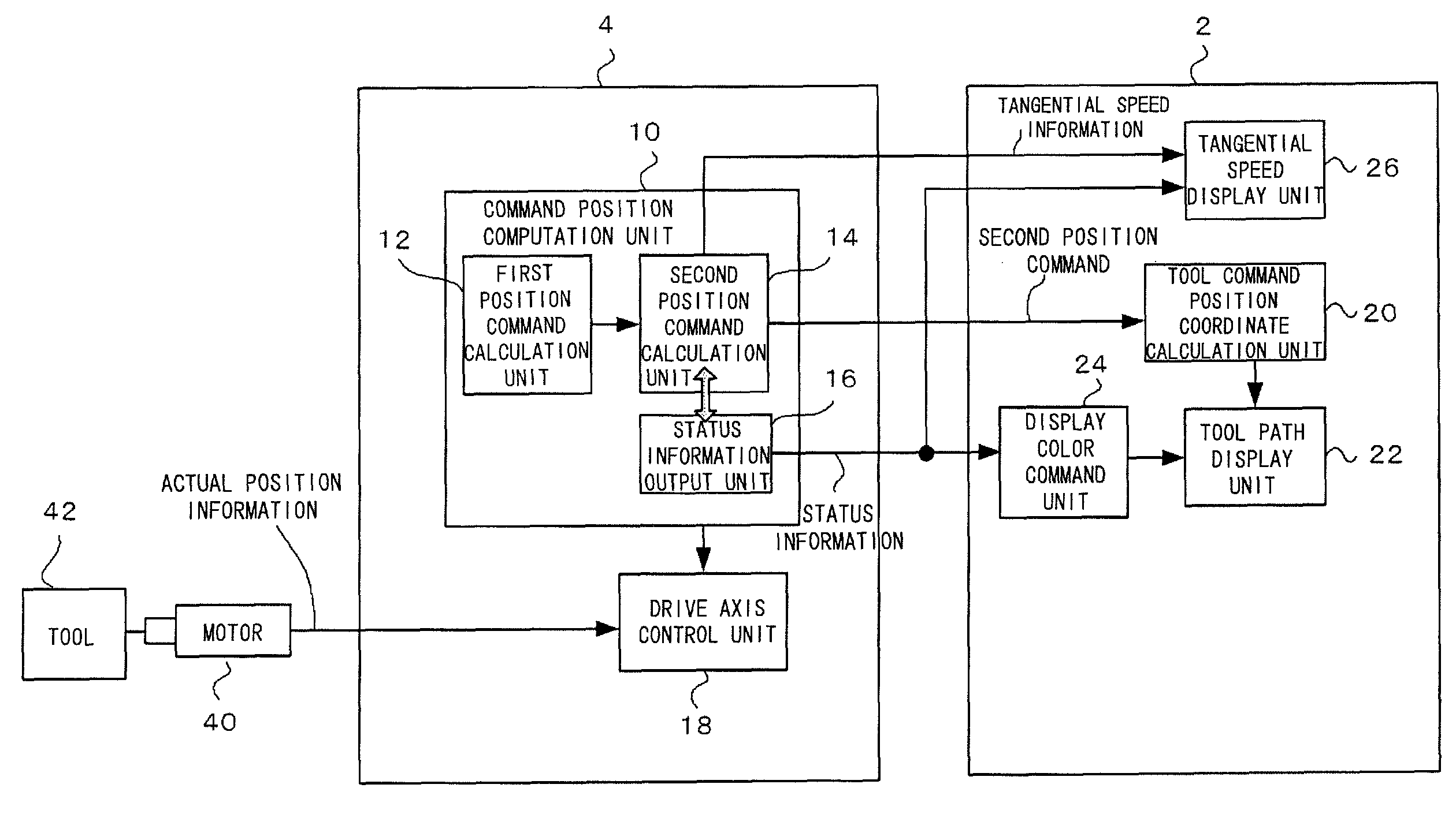
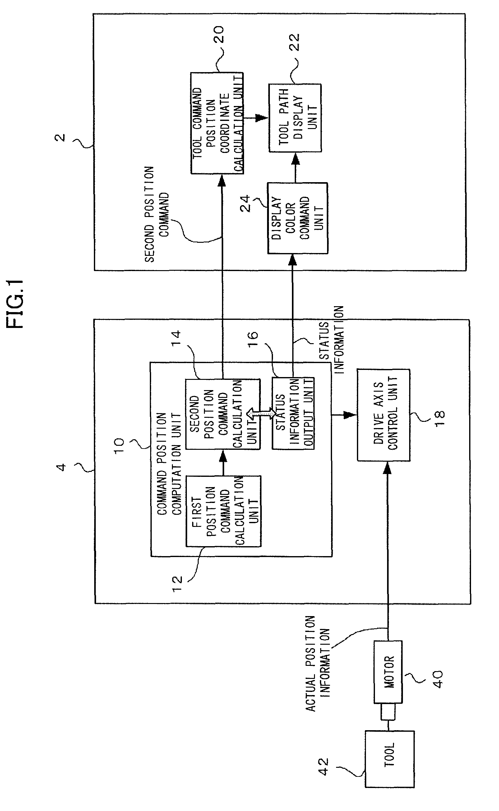
[0025]FIG. 1 is a diagram illustrating a tool, path display apparatus according to the present invention.

[0026]A numerical controller 4 controls a plurality of drive axes of a machine tool in accordance with a machining program and controls the relative positions and postures of a tool relative to a workpiece, thereby enabling the machine tool to machine the workpiece. The numerical controller 4 comprises a command position computation unit 10 and a drive axis control unit 18. The command position computation unit 10 includes a first position command calculation unit 12 configured to calculate a first position command, second position command calculation unit 14 configured to calculate a second position command from the first position command, and status information output unit 16.

[0027]The first position command calculation unit 12 calculates the first position command for a position where a tool 42 is to be located at each time for each drive axis, based on the path shape and tang...

second embodiment

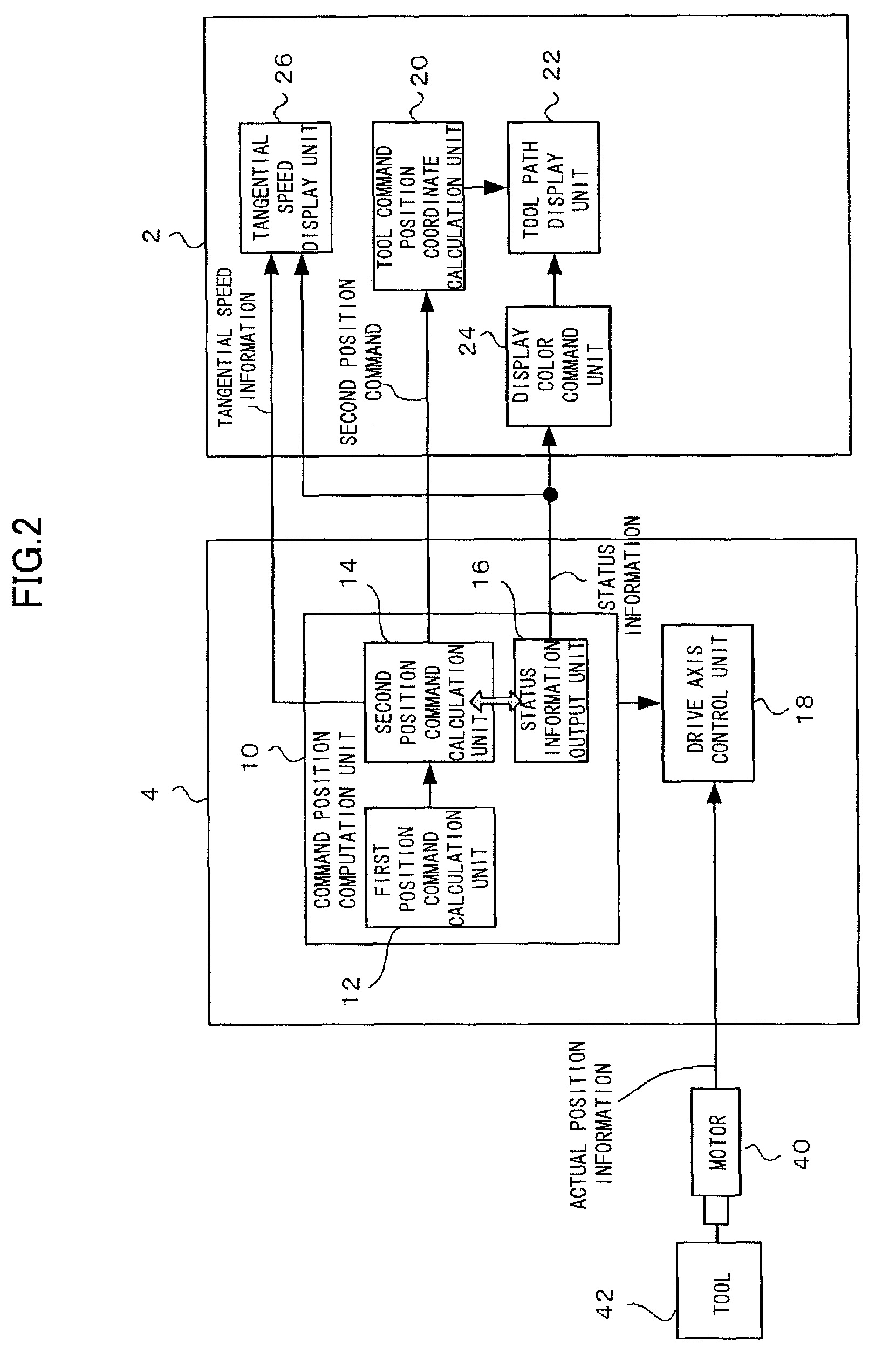
[0031]FIG. 2 is a diagram illustrating the tool path display apparatus according to the present invention, which displays the tangential speed. The tool path display apparatus 2 of this embodiment further comprises a tangential speed display unit 26.

[0032]Referring to FIG. 1, the second position command calculation unit 14 calculates restricted tangential speed information on the tool 42 as it calculates the second position command, and outputs the calculated information to the tangential speed display unit 26. The tangential speed display unit 26 may display the received tangential speed information on the tool 42 in waveforms, as described with reference to FIGS. 7 and 8. Further, the tangential speed display unit 26 can simultaneously display the tangential speed and status information on receiving the status information corresponding to the deceleration conditions from the status information output unit 16.

third embodiment

[0033]FIG. 3 is a diagram illustrating the tool path display apparatus according to the present invention, which displays a path error. The tool path display apparatus 2 of this embodiment further comprises an actual tool position coordinate calculation unit 28, path error calculation unit 30, and path error display unit 32.

[0034]The actual tool position coordinate calculation unit 28 acquires, through the drive axis control unit 18, actual position information detected by an encoder (not shown) attached to the motor 40. Further, the actual tool position coordinate calculation unit 28 calculates two- or three-dimensional coordinate values of the tool as viewed from the coordinate system fixed to the workpiece, based on the actual position of each drive axis of the machine tool at each time and machine configuration information

[0035]The path error calculation unit 30 calculates a path error of the tool 42 based on tool command position coordinate values calculated by the tool command...


PUM


Abstract

A numerical controller calculates a first position command from a machining program, converts the first position command into a second position command for restricting a tangential speed of a tool, and delivers the second position command and a status signal indicative of the achievement of the conversion of the first position command into the second position command to a tool path display apparatus. The tool path display apparatus displays the path of the tool in a color corresponding to the status signal and can thereby determine the point on the tool path at which the speed restriction is performed.

Description

RELATED APPLICATIONS[0001]The present application is based on, and claims priority from, Japanese Application Number 2010-158186, filed Jul. 12, 2010, the disclosure of which is hereby incorporated by reference herein in its entirety.BACKGROUND OF THE INVENTION[0002]1. Field of the Invention[0003]The present invention relates to a tool path display apparatus with deceleration factor identification means for a machine tool.[0004]2. Description of the Related Art[0005]In executing a machining program to machine a workpiece, a tool center point moves at a commanded speed (tangential speed) on a commanded path. However, the tool center point does not always move at the commanded speed, and the speed may be restricted under various conditions depending on the place.[0006]Some machine tool controllers have, for example, a function to restrict the speed of the tool center point so that a speed difference between blocks is not greater than a tolerance that ensures precision machining near c...

Claims


Application Information

Patent Timeline
Patent Type & Authority Patents(United States)
IPC IPC(8): G05B19/25
CPCG05B19/4069
Inventor IWASHITA, YASUSUKEOKITA, TADASHITEZUKA, JUNICHI
Owner FANUC LTD
Features
  • R&D
  • Intellectual Property
  • Life Sciences
  • Materials
  • Tech Scout
  • Unparalleled Data Quality
  • Higher Quality Content
  • 60% Fewer Hallucinations
Learn More