Communications network

Active Publication Date: 2013-04-30
BRITISH TELECOMM PLC
View PDF6 Cites 7 Cited by
  • Summary
  • Abstract
  • Description
  • Claims
  • Application Information

AI Technical Summary

Benefits of technology

[0003]Broadband services are commonly supplied over legacy telephony networks using digital subscriber line (DSL) technology. One of the limitations of DSL is that the maximum data rate is not that high (for example, the maximum bit-rate is around 20 Mb s−1) and that the available bit rate decreases as the distance between the customer and the telephone exchange increases. It is believed that future broadband services are increasingly likely to be offered over optical fibre infrastructure using passive optical network (PON) architectures (D. B. Payne and R. P. Davey, “The future of fibre access systems”, BTTJ, Vol. 20-4, pp 104-114, (2002)). There are a number of large scale PON deployments currently underway around the world using either IEEE EPON technology or FSAN/ITU BPON and GPON. There is an emerging trend from network operators to consolidate network nodes and to reduce the amount of real estate used, leading to reductions in operational costs. A consequence of centralising network equipment into a smaller number of network nodes is that the network is more vulnerable to large scale outages in the event that a node is rendered out of service due to some catastrophic fault (fire, earthquake etc.).
[0004]According to an aspect of the present invention there a communications network comprising first and second optical line terminals and one or more optical network terminals wherein: i) the first optical line terminal has a first network connection to the one or more optical network terminals and the second optical line terminal has a second network connection to the one or more optical network terminals; ii) a virtual LAN connection is made to each of the one or more optical network terminals via the first network connection; and ii) a virtual LAN connection is made to each of the one or more optical network terminals via the second network connection.
[0005]Preferably the network is connected to one or more communications servers, wherein the virtual LAN connections establishe

Problems solved by technology

One of the limitations of DSL is that the maximum data rate is not that high (for example, the maximum bit-rate is around 20 Mb s−1) and that the available bit rate decreases as the distance between the customer and the telephone exchange increases.
A consequence of centralising network equipment into a smaller number of network nodes is that the network is more vulnera

Method used


Image

  • Communications network
  • Communications network
  • Communications network

Examples


Example

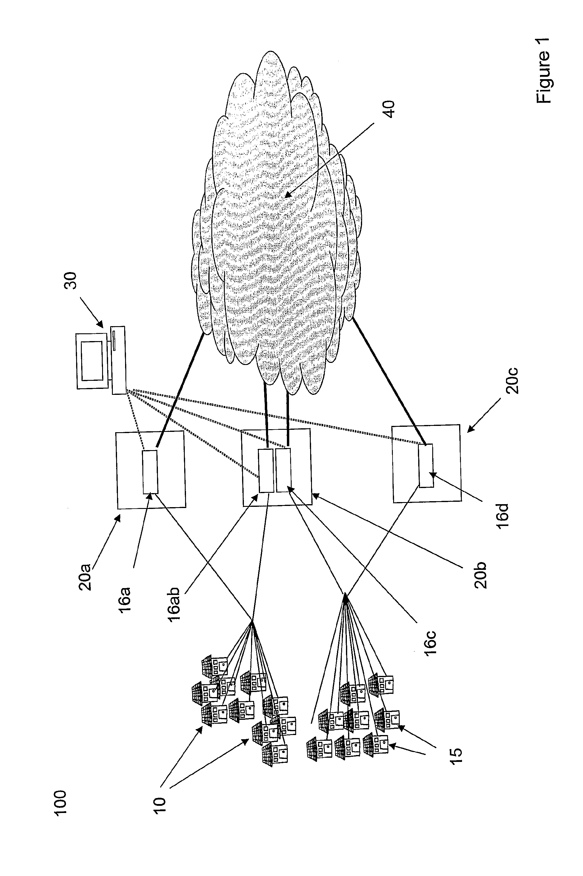
[0012]FIG. 1 shows a schematic depiction of a conventional network architecture that is used to increase the resilience of PONs. A PON 100 comprises a first plurality of optical network terminals (ONTs) 10 and a second plurality of optical network terminals (ONTs) 15. The first plurality of optical network terminals (ONTs) 10 are connected to a first optical line terminal (OLT) at network node 20a via optical fibres and a passive optical splitter. The first OLT 16a is then connected on to a core network 40 for the subsequent routing of traffic. To provide resilience, the first plurality of ONTs is also connected to a second OLT 16b at network node 20b, which is also connected to the core network 40. Similarly, the second plurality of ONTs 15 are connected to a first OLT 16c, which is located at the second network node 20b and to a second OLT 16d which is located at a third network node 20d.

[0013]Conventionally, the first plurality of ONTs will communicate with the first OLT but in ...


PUM


Abstract

A PON in which parallel optical fiber paths are provided between dual OLTs and the ONTs, one of the optical fiber paths providing an active connection and the other optical fiber path providing a standby connection. Respective VLANs may be formed over the parallel optical fiber paths. If performance indicators, for example Ethernet continuity check messages, indicate that an ONT is no longer in communication with the OLT then data may be sent via the VLAN associated with the standby connection.

Description

[0001]This application is the U.S. national phase of International Application No. PCT / GB2008 / 003499 filed 15 Oct. 2008, which designated the U.S. and claims priority to GB Application No. 0720094.2 filed 15 Oct. 2007, the entire contents of each of which are hereby incorporated by reference.BACKGROUND AND SUMMARY[0002]The present invention relates to optical communications networks, and in particular to resilient optical communications networks.[0003]Broadband services are commonly supplied over legacy telephony networks using digital subscriber line (DSL) technology. One of the limitations of DSL is that the maximum data rate is not that high (for example, the maximum bit-rate is around 20 Mb s−1) and that the available bit rate decreases as the distance between the customer and the telephone exchange increases. It is believed that future broadband services are increasingly likely to be offered over optical fibre infrastructure using passive optical network (PON) architectures (D....

Claims


Application Information

Patent Timeline
IPC IPC(8): H04J14/00
CPCH04L12/467H04Q11/0067H04Q2011/0081
Inventor NESSET, DEREKKANG, JUSTINWILKINSON, MARKSMITH, KEVIN
Owner BRITISH TELECOMM PLC
Why Eureka
Try Eureka