Round illumination device

a technology of illumination device and round head, which is applied in the direction of lighting and heating apparatus, optical elements, instruments, etc., can solve the problems of deteriorating the slim appearance of the system, affecting the efficiency of the illumination device, and affecting the illumination effect of the round head, so as to achieve the effect of improving the illumination along the azimuth direction relatively simply

Active Publication Date: 2013-05-07
SIGNIFY HLDG BV
View PDF31 Cites 48 Cited by
  • Summary
  • Abstract
  • Description
  • Claims
  • Application Information

AI Technical Summary

Benefits of technology

[0006]Circular light guides may have the advantage that the collimation along the azimuth direction can relatively simply be improved by increasing the radius of the light outcoupling region with respect to the radius of the source (or light incoupling region). However, for a well-controlled beam also the radial direction needs to be collimated.
[0009]Therefore, there is a desire to provide an alternative flat circular illumination device based on a light guide, and to further improve the beam shape of such flat circular light guides.
[0017]It surprisingly appears that such a device may provide a beam with an advantageous beam shape, which may be well collimated.
[0018]Without being bound to any theory, it seems that by applying, according to a preferred embodiment, elongated structures (herein also indicated as “grooves”) on the first and / or second waveguide surface (also indicated as top and / or bottom surface) of the light guide, along the radial direction in which the light source light is travelling, collimation improves. It seems that by reflection off these grooves, the azimuth direction of a light source light ray is mixed with the direction perpendicular to the guide. While the light is travelling in the radial direction, only the azimuth direction is collimated. The mixing of the two directions ensures that both directions of the light source light will become collimated. Consequently, the beam collimation in both directions will improve with increasing radius, without changing the other optical components, in particular: without increasing the thickness of the system.
[0026]In an embodiment, the light source cavity is closed by one or two caps, selected from the group consisting of diffuser caps and reflector caps. A diffuser cap may improve the light mixing quality of the cavity, i.e. the contributions of individual light sources within the cavity are less distinguishable. This may be particularly important when LEDs of different colours are used. Without a diffuser, unwanted colour effects may be visible to anyone looking into the lamp, but also in the light beam itself (colour variations in the illuminated area, coloured shadows). The diffuser cap(s) and / or reflector cap(s) promote incoupling of the light source light into the waveguide. A diffuser and / or reflector cap may not only cover the light source cavity, but may also cover at least part of the waveguide surface, thereby promoting outcoupling of the light at or close to the edge window. The one or two cavity caps can be considered as (preferred) optional optics.

Problems solved by technology

However, an improved collimation in the radial direction requires larger collimating optics on the LED, which results in a thicker system.
This deteriorates the slim appearance of the system.
For highly collimated beams, this would result in an unwanted increase in thickness of the collimating LED optics, if used.

Method used


Image

  • Round illumination device
  • Round illumination device
  • Round illumination device

Examples


example

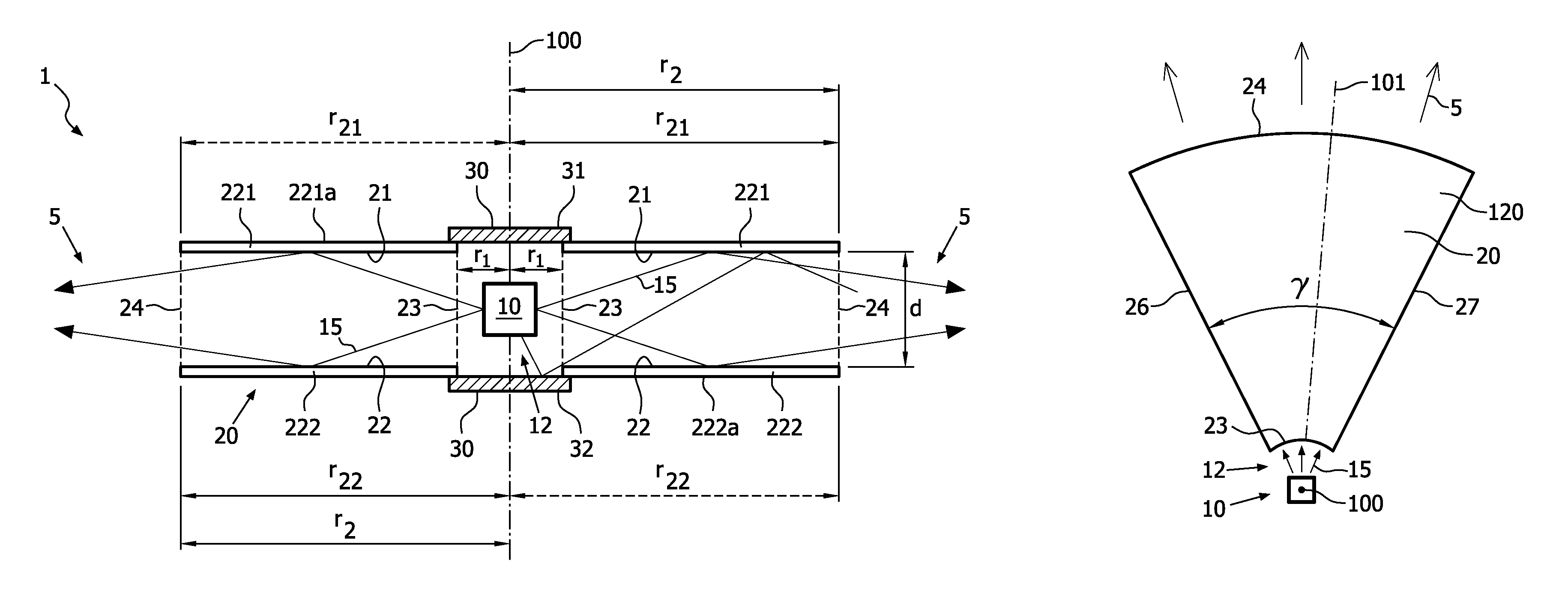
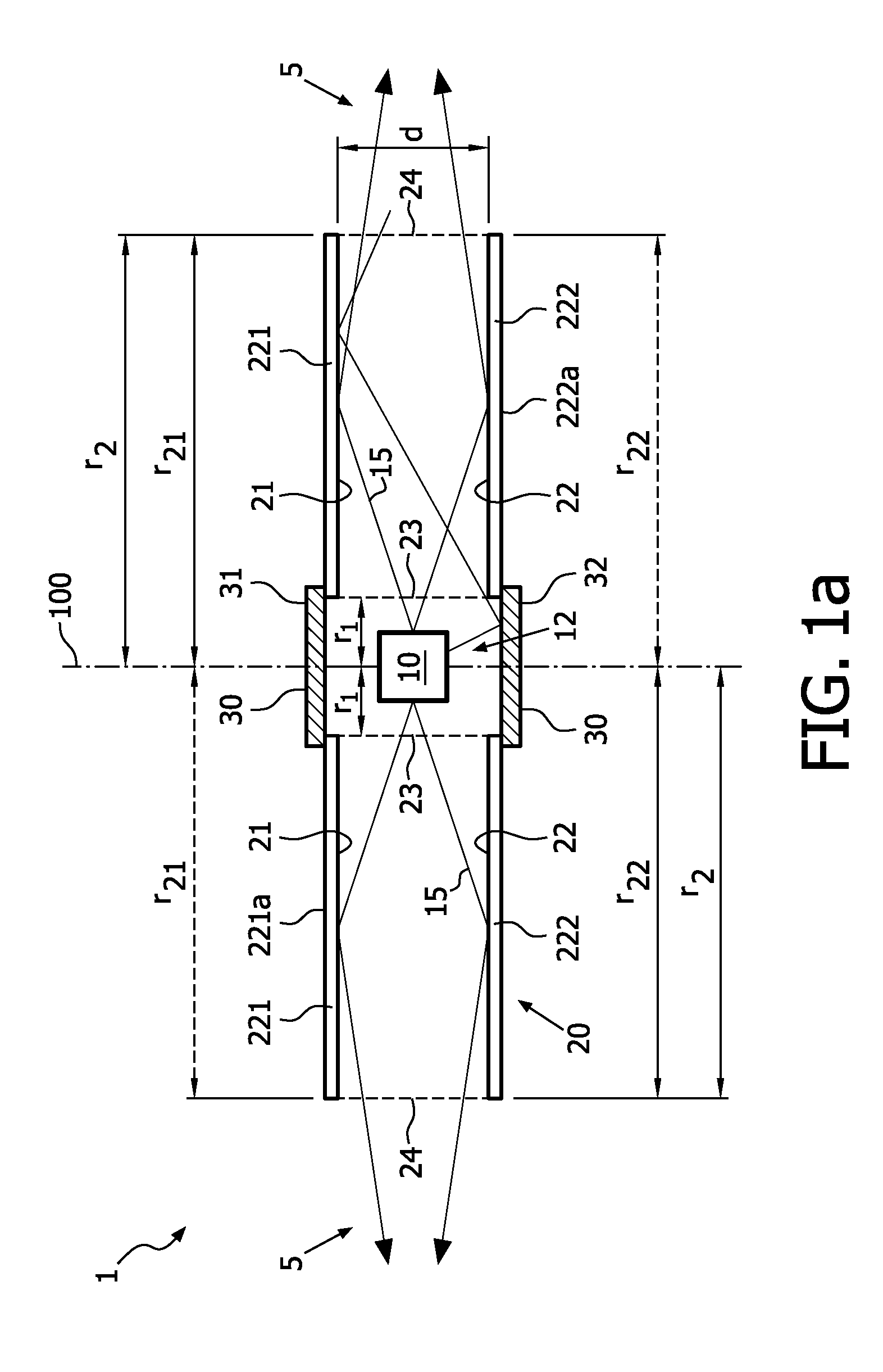
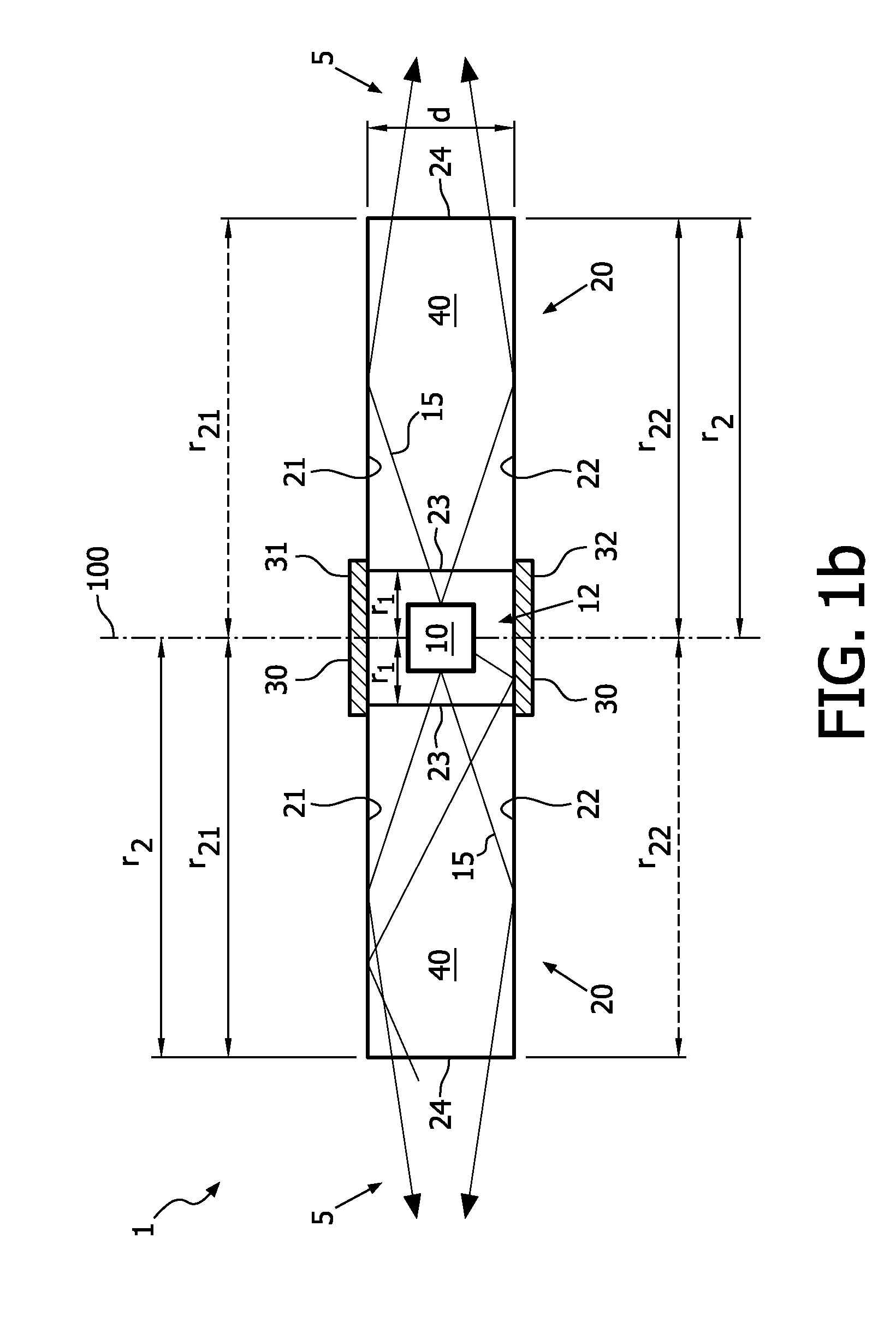
[0106]An illumination device 1 was made, comprising a light source 10 as schematically depicted in FIG. 4g, with 24 Rebel LEDs from LumiLEDs, of which 18 neutral white LEDs 80 lm@1 W LXML-PWN1-0080 and 6 amber LEDs 65 lm@2 W LXML-PL01-0030. The light source 10 emits in radial directions, see FIG. 4g.

[0107]A circular waveguide 20 is arranged around the light source 10, said waveguide having an inner radius r1 of 20 mm, and an outer radius r2 of about 75 mm (in fact radius r21 is 75 mm, since the edge window 24 is slanted). The slant angle of edge window 24 is 45° (radius r22 is thus slightly shorter than radius r21). There is a first cap 31 (here, a reflector) at one side, and a reflecting surface at the other side (not depicted), which is part of an aluminum mechanical substrate that supports the system, and acts as a heat sink. The circular waveguide 20 substantially consists of PMMA (and is thus made of a solid transparent material 40). The thickness d of the waveguide 20 is 5 mm...


PUM


Abstract

The invention provides a substantially round illumination device (1) comprising a light source (10) and a substantially round waveguide (20). The waveguide (20) comprises a first waveguide surface (21), a second waveguide surface (22), a substantially round waveguide entrance window (23), a substantially round waveguide edge window (24), and a central axis (100). The first waveguide surface (21) or the second waveguide surface (22) or both the first waveguide surface (21) and the second waveguide surface (22) further comprise a plurality of elongated structures (200) each having an elongation axis (201) substantially parallel to a radius (101) perpendicular to the central axis (100).

Description

FIELD OF THE INVENTION[0001]The invention relates to a round illumination device comprising a light source and a waveguide arranged to collimate the light, wherein the waveguide comprises a first waveguide surface, a second waveguide surface, a waveguide entrance window, and a waveguide edge window.BACKGROUND OF THE INVENTION[0002]Relatively flat and round light sources are known in the art and are for instance described in U.S. Pat. No. 7,025,482 and U.S. Pat. No. 7,181,378.[0003]U.S. Pat. No. 7,025,482 for instance describes a light guide member and an illuminating device which are able to efficiently and uniformly radiate illumination light to only an area requiring illumination. Therefor, a reflection face is formed by reflection stripes, such as a large number of grooves, etc. widened in a concentric circle shape. Light from a light source unit is widened toward this entire reflection face without irregularities by a diffusing portion such as a reflection prism, etc. Thus, only...

Claims


Application Information

Patent Timeline
Patent Type & Authority Patents(United States)
IPC IPC(8): F21V5/00
CPCG02B6/0021G02B6/0038G02B6/0048
Inventor VISSENBERG, MICHEL CORNELIS JOSEPHUS MARIE
Owner SIGNIFY HLDG BV
Why Eureka
Try Eureka