
Pellicle

a technology of pellicle and spherical shell, which is applied in the field of pellicle, can solve the problems of difficult to keep the photomask clean all the time, damage to the photomask, rough edges or black spots, etc., and achieve the effects of reducing the number of ventilation holes, and reducing the amount of dust generated by the filter member

Active Publication Date: 2013-05-07
SHIN ETSU CHEM IND CO LTD
View PDF5 Cites 3 Cited by
  • Summary
  • Abstract
  • Description
  • Claims
  • Application Information

AI Technical Summary

Benefits of technology

The present invention provides a pellicle with less dust generation and excellent ventilation characteristics. The filter member has an adhesive layer or a pressure-sensitive adhesive layer for bonding to the outer stepped portion, which increases the gap under the filter surface to improve ventilation. The filter member is protected from protruding from the pellicle frame outer face or contact and breakage during handling. The outer stepped portion makes a target of an attachment position when the filter member is attached, accurately attachment to the position is made possible even without a special technique. The depth of the outer stepped portion is preferably within a range of 50 to 150% of the filter member thickness, to prevent breakage of the filter member. The filter member is attached inside the outer stepped portion, resulting in a pellicle with high ventilation characteristics, reduced risk of contact and breakage, and improved workability during manufacture. The deployment of the filter member is facilitated, and even a large number of filter members can be installed in a short time with high reliability.

Problems solved by technology

In manufacture of a semiconductor including LSI, super LSI and the like or in manufacture of a liquid crystal display or the like, a pattern is made by irradiating light to a semiconductor wafer or an original plate for liquid crystal, but if a dust adheres to a photomask or a reticle (hereinafter simply referred to as a photomask in short) used at this time, the dust absorbs light or refracts the light, which causes deformation of a transferred pattern, rough edges or black stains on a base and leads to a problem that dimensions, quality, appearance and the like are damaged.
Thus, these works are usually performed in a clean room, but it is still difficult to keep the photomask clean all the time.
However, to provide a large number of ventilation holes in order to ensure the ventilation amount results in deterioration of rigidity of the pellicle frame, which is not preferable.
If the rigidity is lowered, deformation can easily occur during manufacture, deflection of the frame when the pellicle film is extended becomes large, which leads to a problem that an effective exposure area inside the pellicle is reduced or accuracy of pellicle attachment is deteriorated.
That is, the larger the application amount is, the better the dust-generation prevention effect, but the ventilation characteristics are deteriorated.
Thus, it has been extremely difficult to ensure high ventilation capacity while a high dust-generation prevention effect is maintained.
However, if the number of installed filter members is increased, various problems occur such as a burden of an installation work or the like.
If a large number of filter members protrude outside the pellicle frame, a risk is considerably increased that the filter member might touch a handling jig, a pellicle attaching device or an exposing device and is damaged or the pellicle frame is pushed inward for a thickness of the filter member and this causes a wrinkle in the pellicle film.
Moreover, there is a problem in manufacture.
However, since the filter member is usually as thin as approximately 0.15 to 0.3 mm, the member should be attached with utmost care so that the film surface is not stained or damaged, and the work is extremely difficult.
Therefore, if the number of members to be attached is large, the filter member attachment work has a particularly big burden on workers.

Method used


Image

  • Pellicle
  • Pellicle
  • Pellicle

Examples


example 1

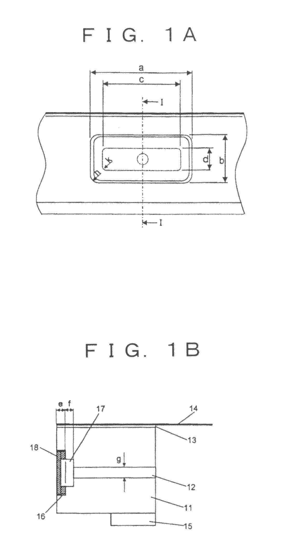
[0048]From a rolled plate made of A5052 aluminum alloy, a pellicle frame with an outer dimension of 1526×1748 mm, an inner dimension of 1493×1711 mm, and a height of 6.2 mm and a shape as shown in FIG. 7A was manufactured by machine work. FIG. 7A is a plan view and FIG. 7B is a sectional view by I-I line of a pellicle frame 71. In this pellicle frame, 16 ventilation holes were disposed so that each ventilation hole might have a sectional shape as shown in FIG. 1B. Here, the dimensions in the figure are the outer stepped portion (a, b, e)=10.0×4.0×0.3 mm, the inner stepped portion (c, d, f)=7.5×1.6×0.5 mm, the ventilation hole diameter (g)=1.5 mm, a radius of curvature (h) of an outer edge corner part of the outer stepped portion=1.0 mm, and a radius of curvature (k) of an outer edge corner part of the inner stepped portion=0.5 mm. Then, after the machine work is finished, the pellicle frame surface was sandblast-treated, and further applied with black anodization treatment.

[0049]Thi...

example 2

[0061]A pellicle was manufactured with the same method and procedure as those in Example 1. However, a silicone pressure-sensitive adhesive was not applied to the filter member to be used. For this pellicle, appearance inspection and ventilation characteristics evaluation were made similarly to Example 1.

[0062]An appearance of the filter member of the completed pellicle was observed and turned out that all the filter members were accommodated in the steps and favorable without bending or misalignment.

[0063]As the ventilation characteristics evaluation, the device in FIG. 8 introduced 5000 cc of air into the pellicle, and time till the pellicle film returned to the original height was measured, and the result was 14 hr. 40 min.


PUM

PropertyMeasurementUnit
depthaaaaaaaaaa
depthaaaaaaaaaa
thicknessaaaaaaaaaa

Abstract

There is provided a pellicle having a rectangular pellicle frame formed of four side bars, having a through hole made through at least one of the frame bars for adjusting a pressure of a space formed within the pellicle frame equal to a pressure outside the pellicle frame; and a filter member disposed to cover up an external opening of the through hole for preventing entrance of particles into the space, wherein the through hole is formed with:(1) an outer stepped portion defining a first recess, opening outside the pellicle frame, for accommodating the filter member,(2) an inner stepped portion defining a second recess, opening in a bottom of the first recess, and(3) a ventilation hole with one end opening in a bottom of the second recess of the inner stepped portion and the other end opening in the space within the pellicle frame.

Description

RELATED APPLICATIONS[0001]The present application is claims priority from Japanese Application No. 2009-152277, filed Jun. 26, 2009, the disclosure of which is hereby incorporated by reference herein in its entirety.FIELD OF THE INVENTION[0002]The present invention relates to a pellicle used as a dustproof when a semiconductor device, a printed circuit board, a liquid crystal display and the like are manufactured.BACKGROUND[0003]In manufacture of a semiconductor including LSI, super LSI and the like or in manufacture of a liquid crystal display or the like, a pattern is made by irradiating light to a semiconductor wafer or an original plate for liquid crystal, but if a dust adheres to a photomask or a reticle (hereinafter simply referred to as a photomask in short) used at this time, the dust absorbs light or refracts the light, which causes deformation of a transferred pattern, rough edges or black stains on a base and leads to a problem that dimensions, quality, appearance and the...

Claims


Application Information

Patent Timeline
Patent Type & Authority Patents(United States)
IPC IPC(8): G03F1/62G03F1/64
CPCG03F1/64G03F1/62H01L21/0275
Inventor SEKIHARA, KAZUTOSHI
Owner SHIN ETSU CHEM IND CO LTD
Learn More