Rotary current-collecting device and rotating anode X-ray tube

a current collection and rotary technology, applied in the direction of x-ray tubes, x-ray tube details, acyclic motors, etc., can solve the problems of poor self-lubricating properties of glassy carbon and unsuitable mechanical sliding parts, and achieve low friction coefficient, less dust generation, and low electrical resistance

Active Publication Date: 2005-04-21
RIGAKU CORP
View PDF8 Cites 6 Cited by
  • Summary
  • Abstract
  • Description
  • Claims
  • Application Information

AI Technical Summary

Benefits of technology

[0011] The properties required for the material of the collector and the brush of the rotary current-collecting device are believed to be a low friction coefficient, a low electrical resistance and a corrosion resistance, the glassy carbon satisfying these properties. The glassy carbon shows less dust generation too, it also being advantageous for the rotary current-collecting device. The combination of the collector made of the glassy carbon and the brushes made of graphite or a metal-graphite compound has useful properties of: making no oxide layer; a corrosion resistance; a low electrical contact resistance; a low friction coefficient; and less dust generation. Therefore, the combination gives a good performance as the rotary current-collecting device. The thus configured rotary current-collecting device can be incorporated into a rotating anode X-ray tube.
[0012] Since the rotary current-collecting device according to the present invention has the collector made of glassy carbon, an amount of brush abrasion is reduced, the dust generation is low, and the lifetime of the rotary current-collecting device is prolonged in comparison with the prior art.

Problems solved by technology

It is said that the glassy carbon has a poor self-lubricating property and accordingly it is not suitable for mechanical sliding parts.

Method used


Image

  • Rotary current-collecting device and rotating anode X-ray tube
  • Rotary current-collecting device and rotating anode X-ray tube
  • Rotary current-collecting device and rotating anode X-ray tube

Examples


Embodiment Construction

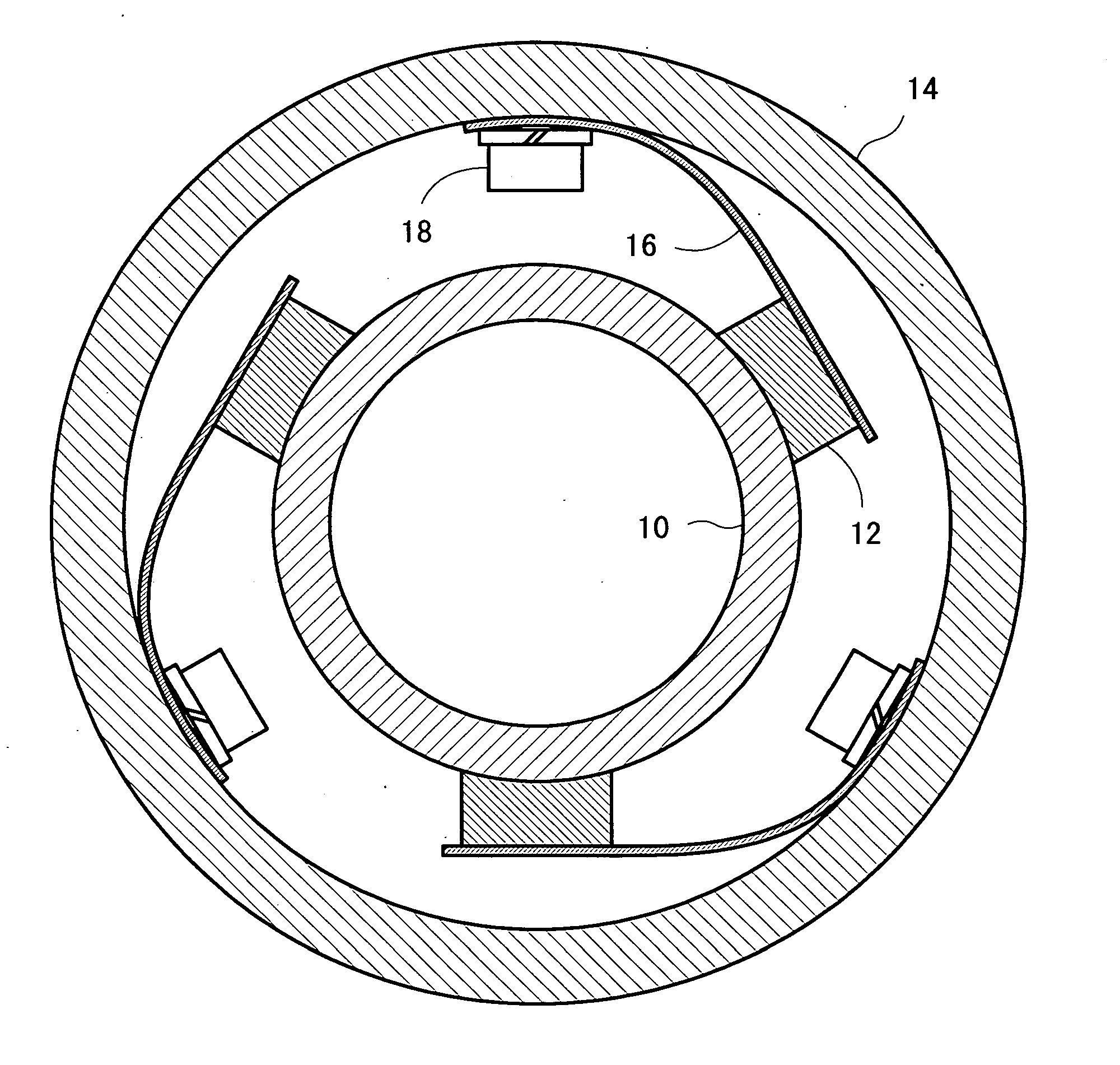
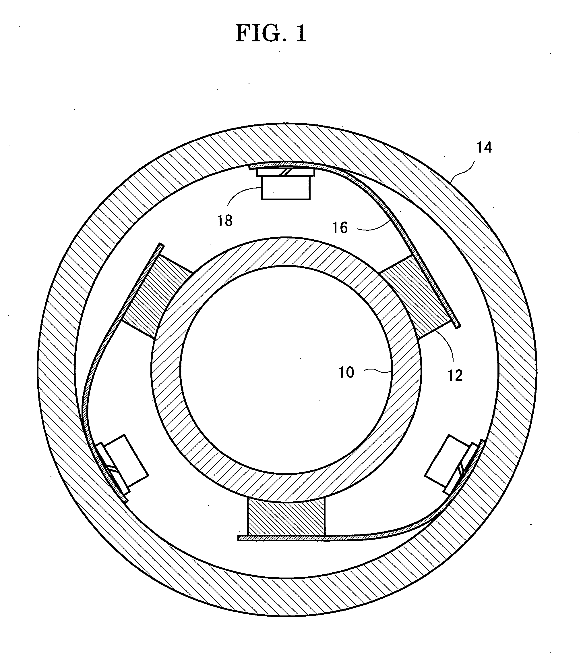
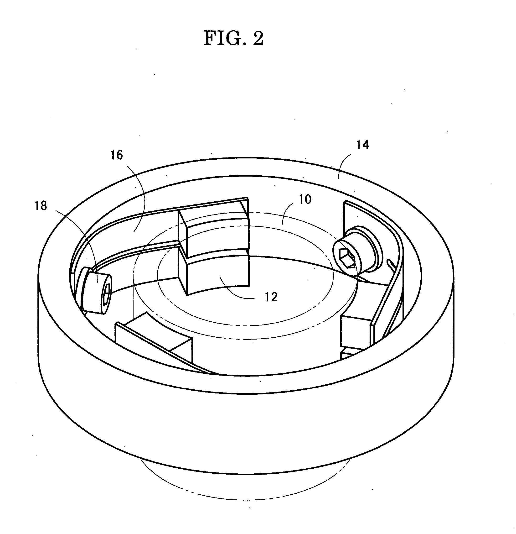
[0017] Embodiments of the present invention will now be described with reference to the drawings. First, the shape of a rotary current-collecting device will be described. Referring to FIG. 1, a rotary current-collecting device has a slip ring 10 and brushes 12. The slip ring 10 has a cylindrical shape with an outside diameter of 20 mm. The outer peripheral surface of the slip ring 10 is a sliding-contact surface which is to come into sliding contact with the brushes 12. A brush-holding ring 14 has a cylindrical shape larger than the slip ring 10. The inner surface of the brush-holding ring 14 supports three brush-holding springs 16 in an equally spaced arrangement. The root of the brush-holding spring 16 is fixed to the brush-holding ring 14 by screws 18. Referring to FIG. 2, the brush-holding spring 16 has a tip end which is divided into two parts each of which fixedly supports the brush 12. The brushes 12 are pushed against the outer peripheral surface of the slip ring 10 under t...


PUM


Abstract

A rotary current-collecting device includes a rotary slip ring and brushes coming into sliding contact with the outer peripheral surface of the slip ring. The brush-holding ring has an inner surface to which three brush-holding springs are fixed by screws. Each of the brushes is fixed to the tip end of the brush-holding spring and is pushed against the outer surface of the slip ring under the resilient restoration force of the brush-holding spring. When the slip ring revolves, the brushes come into sliding contact with the outer peripheral surface of the slip ring. The brush is made of a metal-graphite compound consisting of 70 weight percent copper and 30 weight percent graphite. The slip ring is entirely made of glassy carbon, so that the brush abrasion can be reduced.

Description

BACKGROUND OF THE. INVENTION [0001] 1. Field of the Invention [0002] The present invention relates to a rotary current-collecting device having a combination of a collector and brushes, and more especially to a rotary current-collecting device characterized by the material of the collector. The present invention also relates to a rotating anode X-ray tube having such a rotary current-collecting device. [0003] 2. Description of the Related Art [0004] The rotary current-collecting device is known as typically a combination of a commutator and brushes as in a electric motor or a combination of a slip ring and brushes for power supply to a rotary shaft. The commutator and the slip ring are rotary members which are called as a collector. On the other hand, the brushes are stationary members which come into sliding contact with an outer peripheral surface of the collector. An electric current flows between the collector and the brushes during the sliding contact. [0005] The collector and ...

Claims


Application Information

Patent Timeline
Patent Type & Authority Applications(United States)
IPC IPC(8): H01R39/20H01J35/10H01R39/08H02K13/00
CPCH01J35/10H01R39/20H01R39/085H01J2235/102
Inventor KURIBAYASHI, MASARUCHAKI, TOMOHIRO
Owner RIGAKU CORP
Why Eureka
Try Eureka