System and method for coherent detection of optical signals

a technology of optical signals and coherent detection, applied in the field of dpsk optical communication systems, can solve the problems of not providing the desired robustness of the dispersion accumulated by dpsk optical signals

Inactive Publication Date: 2013-05-07
GOOGLE LLC
View PDF10 Cites 54 Cited by
  • Summary
  • Abstract
  • Description
  • Claims
  • Application Information

AI Technical Summary

Benefits of technology

[0017]The applicant has found that the combination of the above coherent optical receiving device, the above electrical filter and the above squarer allows to efficiently receive and decode a DPSK optical signal while at the same time improving the dispersion robustness of the received DPSK optical signal.
[0060]Advantageously this configuration avoids the need of a respective polarization matching system within each of the two receiving systems.
[0062]According to a still further aspect of the present invention, a bidirectional optical communication system comprises a first and a second optical communication system in any of the above aspects, wherein the receiving system of the first communication system is located at a first site wherein the transmitter of the second communication system is located and the receiving system of the second communication system is located at a second site wherein the transmitter of the first communication system is located. In this way it is advantageously possible to use a single laser source at each of the first and second site, the single laser source acting both as the respective laser source and the respective local oscillator.

Problems solved by technology

The Applicant has noted that the optical coherent receivers disclosed in Davis et al for receiving a DPSK optical signal, such as for example the phase diversity receiver of FIGS. 7 and 11 of the article, do not provide the desired robustness to the dispersion accumulated by the DPSK optical signal during propagation from the transmission to the reception.

Method used


Image

  • System and method for coherent detection of optical signals
  • System and method for coherent detection of optical signals
  • System and method for coherent detection of optical signals

Examples


first embodiment

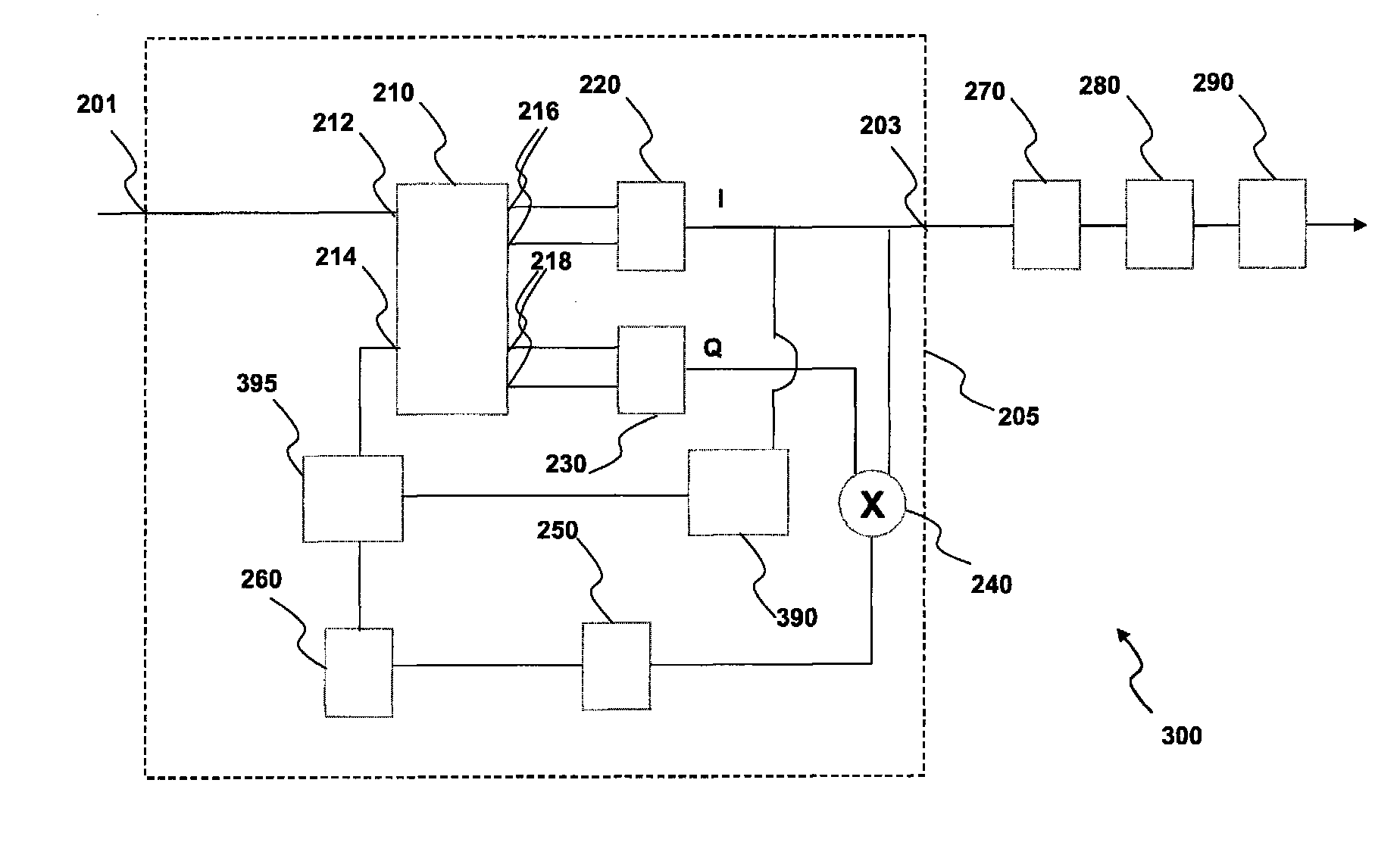
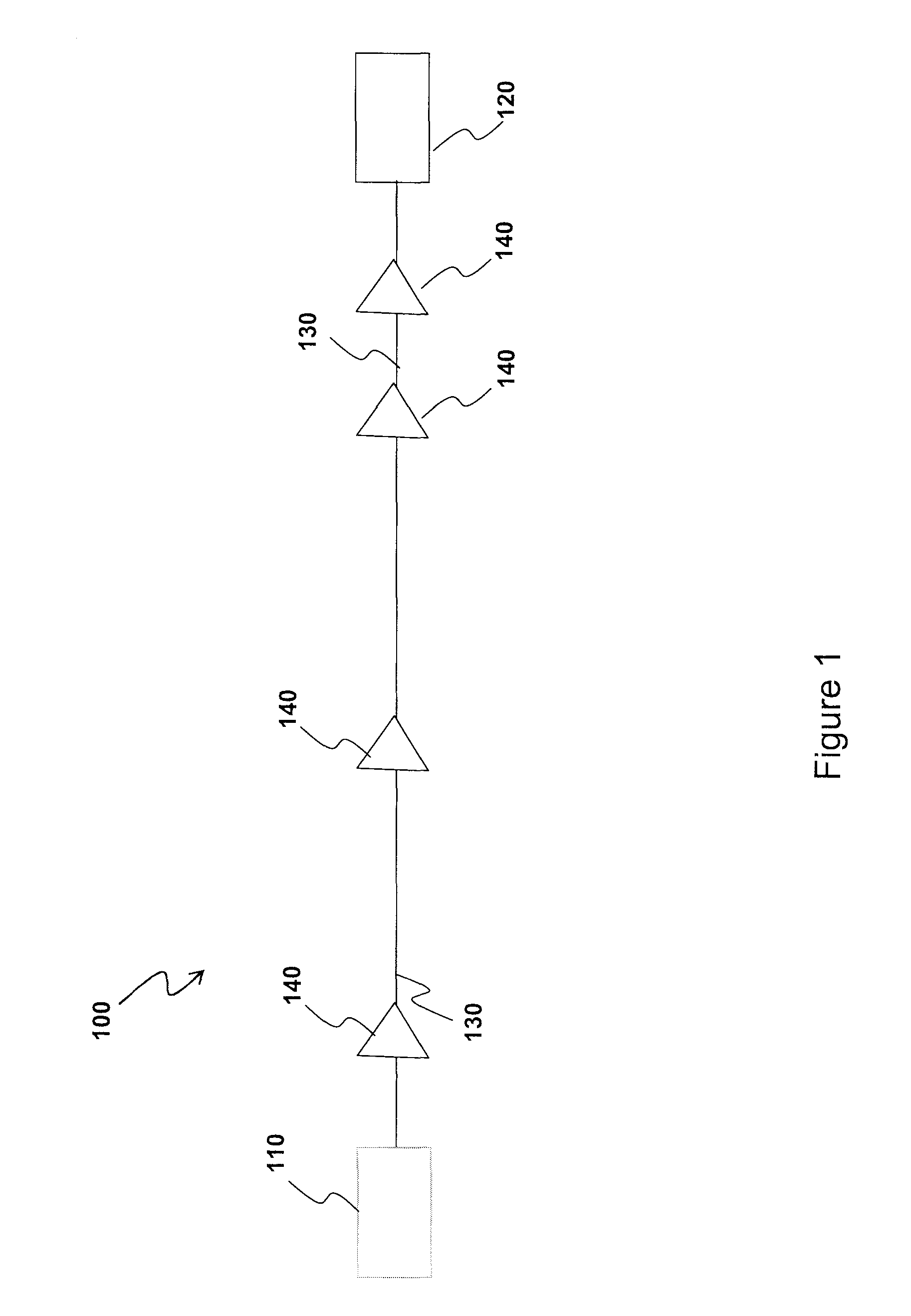
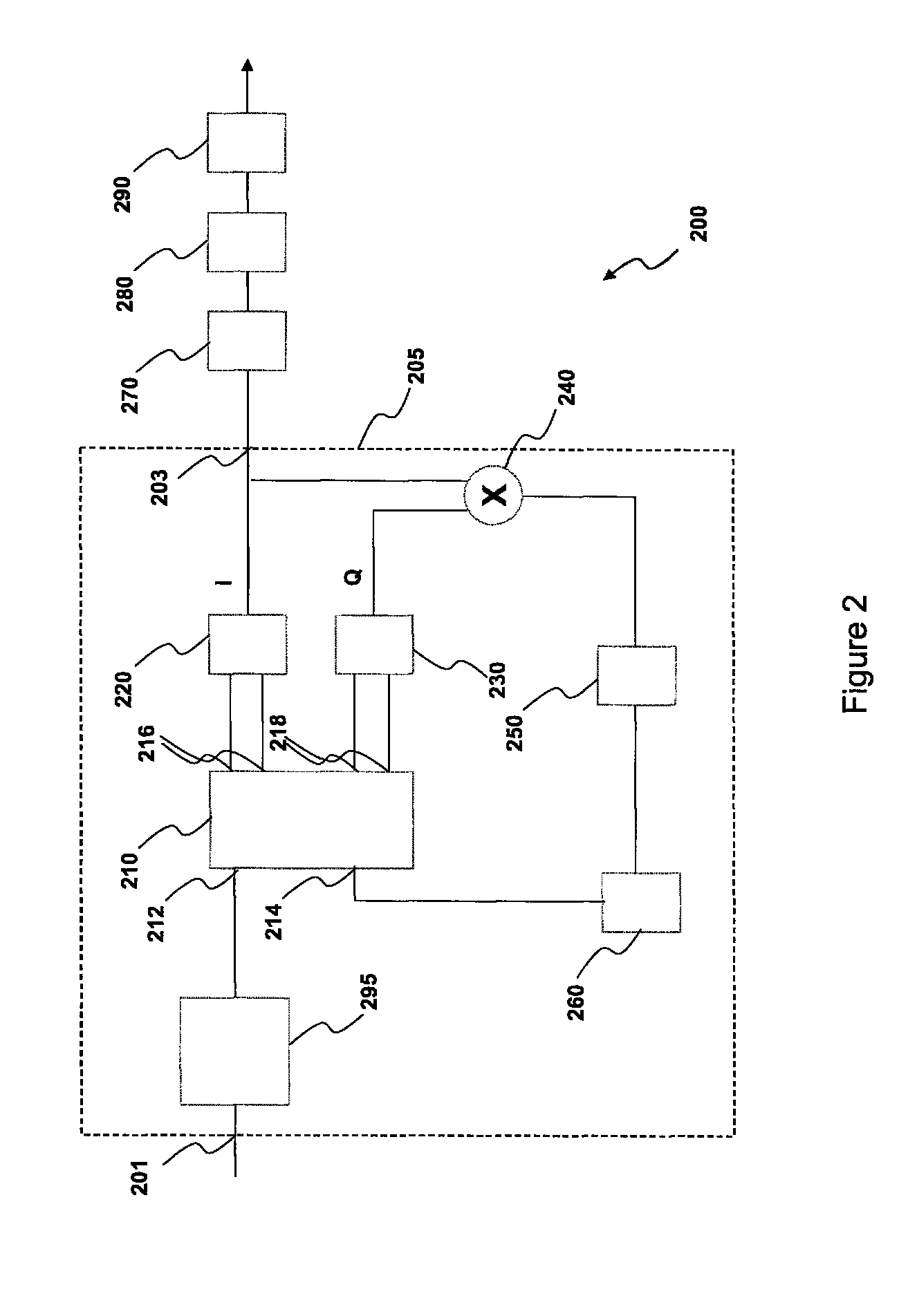
[0095]FIG. 2 shows a schematic diagram of an optical receiving system 200 in accordance with the present invention. The optical receiving system 200 is comprised within the end apparatus 120 of FIG. 1.

[0096]The optical receiving system 200 comprises a coherent optical receiving device 205 based on a homodyne coherent receiving architecture with Costas optical phase locked loop (OPLL). The device 205 has an optical input port 201 optically connectable to the optical link 130 and an electric output port 203.

[0097]The coherent optical receiving device 205 comprises an optical hybrid 210 having a first input port 212 optically connected to the input port 201 and a second input port 214 optically connected to a local oscillator 260. The optical hybrid 210 further has a first pair of output ports 216 optically connected to a first differential photodetector 220 for outputting in-phase components (0° and 180°) of the optical signal with respect to the local oscillator and a second pair of ...

second embodiment

[0126]FIG. 9 shows a schematic diagram of an optical receiving system 900 in accordance with the present invention.

[0127]The optical receiving system 900 comprises a heterodyne coherent optical receiving device 905 based on a heterodyne coherent receiving architecture. The receiving device 905 having an optical input port 901 optically connectable to the optical link 130 and an electric output port 903.

[0128]The coherent optical receiving device 905 comprises an optical hybrid 910 having a first input port 912 optically connected to the input port 901 and a second input port 914 optically connected to a local oscillator 260. The optical hybrid 910 further has a first output port 916 optically connected to a first input of a differential photodetector 920 and a second output port 918 optically connected to a second input of the differential photodetector 920, for outputting both in-phase (0° and 180°) components of the optical signal with respect to the local oscillator. The optical ...

third embodiment

[0146]FIG. 12 shows a schematic diagram of an optical receiving system 1200 in accordance with the present invention. The optical receiving system 1200 is comprised within the end apparatus 120 of FIG. 1. The optical receiving system 1200 comprises a phase diversity coherent optical receiving device 1205 having an optical input port 1201 optically connectable to the optical link 130 and a first and a second electric output port 1203, 1204.

[0147]The coherent optical receiving device 1205 comprises an optical hybrid 210, a local oscillator 260, a first and a second differential photodetector 220, 230 as shown and described with reference to FIG. 2. In an alternative configuration (not shown), the first and second photodetector 220 and 230 are single-input photodetector with AC output each one coupled to one output port of, respectively, the first and second pair of output ports 216 and 218, as described above.

[0148]In a still further alternative configuration, the optical hybrid 210 m...


PUM


Abstract

An optical communication system (100; 2300) comprises at least a transmitter (110) apt to emit a differential phase shift keying (DPSK) optical signal having a bit-rate equal to R, at least a receiving system (1200) for receiving the differential phase shift keying optical signal; and an optical link (130) optically connecting the transmitter and the receiving system for transmitting the DPSK optical signal from the transmitter to the receiving system, wherein the receiving system comprises a coherent optical receiving device (1205) apt to coherently receive the propagated DPSK optical signal and to emit at least one electrical signal (I) related to the received DPSK optical signal, and wherein the receiving system further comprises at least one electrical filter (270) for filtering the at least one electrical signal and having −3 dB double-side bandwidth greater than or equal to 0.44 R and lower than or equal to 0.68 R, and at least one squarer (280) for squaring the at least one filtered electrical signal. A related method for optical communication is also disclosed.

Description

RELATED APPLICATION[0001]This application is the U.S. National Stage of International Application No. PCT / IB2007 / 054948, filed Dec. 6, 2007, which designates the U.S., published in English. The entire teachings of the above application are incorporated herein by reference.FIELD OF THE INVENTION[0002]The present invention relates to the field of DPSK optical communication systems based on optical coherent receiving techniques.BACKGROUND OF THE INVENTION[0003]Coherent optical detection in optical communication systems provides a receiver sensitivity greatly enhanced with respect to direct detection (DD) schemes.[0004]In coherent receivers the optical signal interferes with a local oscillator (which is locked to the signal both in polarization and in phase or frequency) and the beating term, which contains the information of the optical signal, is then directly detected by a photodiode. The local oscillator has an optical power greatly higher than the power of the optical signal and it...

Claims


Application Information

Patent Timeline
Patent Type & Authority Patents(United States)
IPC IPC(8): H04B10/00H04B10/61H04B10/63H04B10/64
CPCH04B10/61H04B10/6161H04B10/6162H04B10/63H04B10/64
Inventor BOFFI, PIERPAOLOMARAZZI, LUCIAMARTELLI, PAOLOPAROLARI, PAOLARIGHETTI, ALDO
Owner GOOGLE LLC
Why Eureka
Try Eureka