Active cancellation and vibration isolation with feedback and feedforward control for an aircraft engine mount

a technology of active cancellation and vibration isolation, which is applied in the direction of vibration suppression adjustment, mechanical equipment, transportation and packaging, etc., can solve the problems of engine fundamental frequency noise generation, tonal noise generation, and engine vibration, so as to prevent engine vibration and dissipate the dynamic energy of tonal vibration

Active Publication Date: 2013-05-14
GENERAL ELECTRIC CO
View PDF17 Cites 13 Cited by
  • Summary
  • Abstract
  • Description
  • Claims
  • Application Information

AI Technical Summary

Benefits of technology

[0008]In an embodiment of the present invention, active vibration mechanisms are attached in the vicinity of the engine mounts to prevent engine vibrations from propagating into the engine mounting structure, for example, the wing or fuselage structure, depending how the engines are mounted. In an embodiment, the active vibration mechanisms are powered actuators attached to the structure in the vicinity of, or embedded within, the engine mount to inject anti-vibration movements to cancel the tonal vibrations generated by the engine. In another embodiment, the active vibration mechanisms are powered actuators attached to the structure in the vicinity of, or embedded within, the engine mount to dissipate the dynamic energy of the tonal vibrations generated by the engine.

Problems solved by technology

In aircraft cabins, tonal noise is generated by the fundamental frequencies of engine rotations.
The generation of this noise has been an issue for many years.
The tonal noise is caused by residual imbalances in the engines rotating parts, such as low and high speed turbines, fan blades, compressors, etc.
Even though the imbalance from rotating parts, including shafts and blades, are closely controlled in manufacturing, due to improved manufacturing methods, the imbalance can still develop due to changes in operation, or through deterioration of the system over time.
It is these kinds of vibrations which propagate through wing and / or fuselage structure and produce annoying low frequency tonal noise in the aircraft cabin.
This tonal noise is usually a major contributor to the overall cabin noise level.
Psychoacoustics analysis indicates that an individual can be easily fatigued if exposed to low frequency noises, especially with long time exposure, such as in the long range air travel.
It is understood that these tonal vibrations cannot be avoided.
However, during the operation, the balance can change, introducing an imbalance into the structure.
The system deterioration with service time can also introduce imbalance.
The imbalance-induced vibrations transmit through the engine mount, wing structures, fuselage structures, and finally excite the cabin interior structures, such as trim panels.
Traditionally, “soft” (i.e. flexible or shock absorbing) engine mounts have been the least expensive and most effective way to reduce the vibration transmission.
Such a “soft” mount design results in a large displacement during the engine speed up, which is undesirable and air frame manufacturers wish to avoid.
Further, the reliability and durability of soft engine mounts is an issue, as their reliability and durability are less than hard engine mounts.

Method used


Image

  • Active cancellation and vibration isolation with feedback and feedforward control for an aircraft engine mount
  • Active cancellation and vibration isolation with feedback and feedforward control for an aircraft engine mount
  • Active cancellation and vibration isolation with feedback and feedforward control for an aircraft engine mount

Examples


Embodiment Construction

[0018]The present invention will be explained in further detail by making reference to the accompanying drawings, which do not limit the scope of the invention in any way.

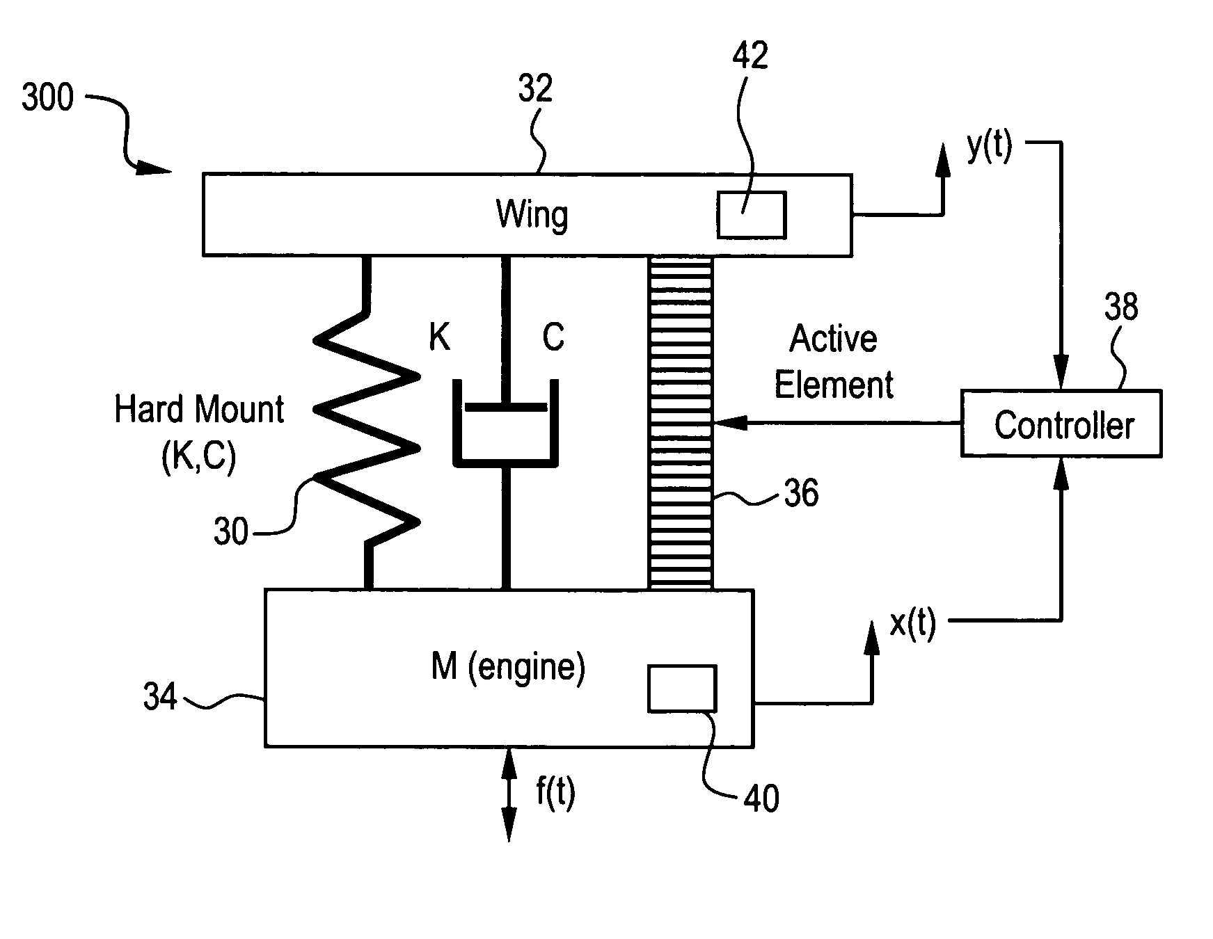
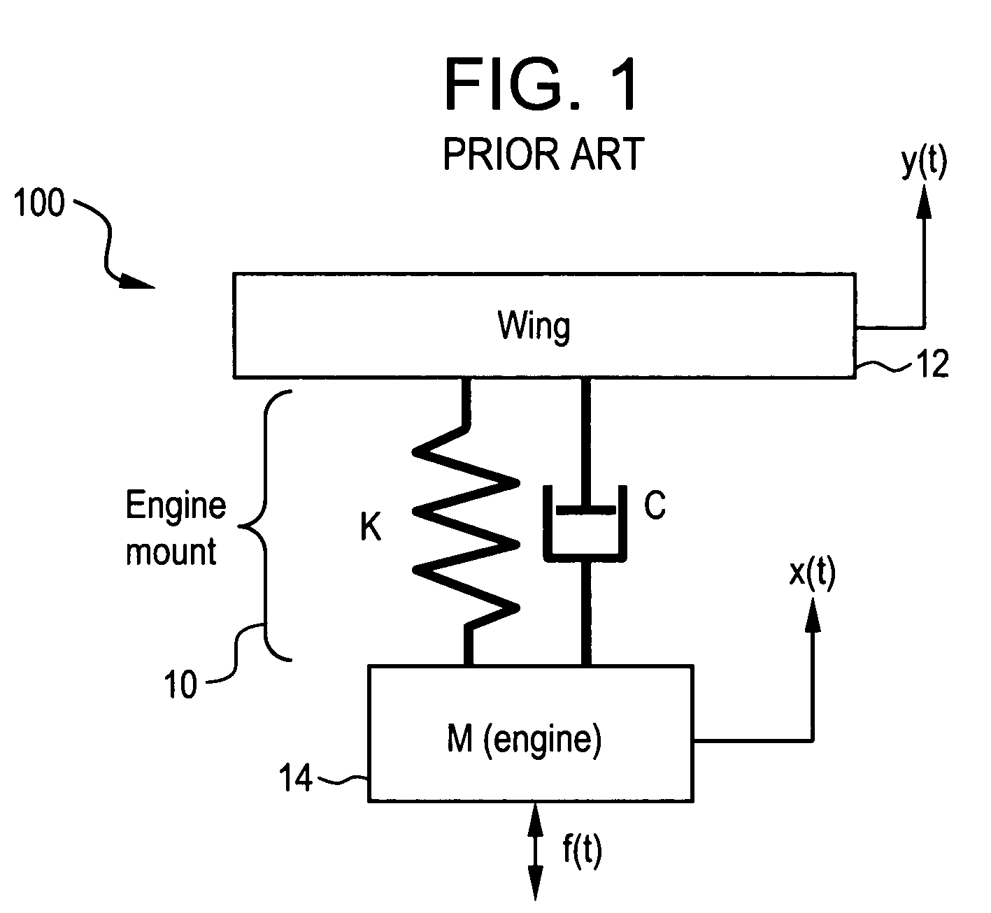
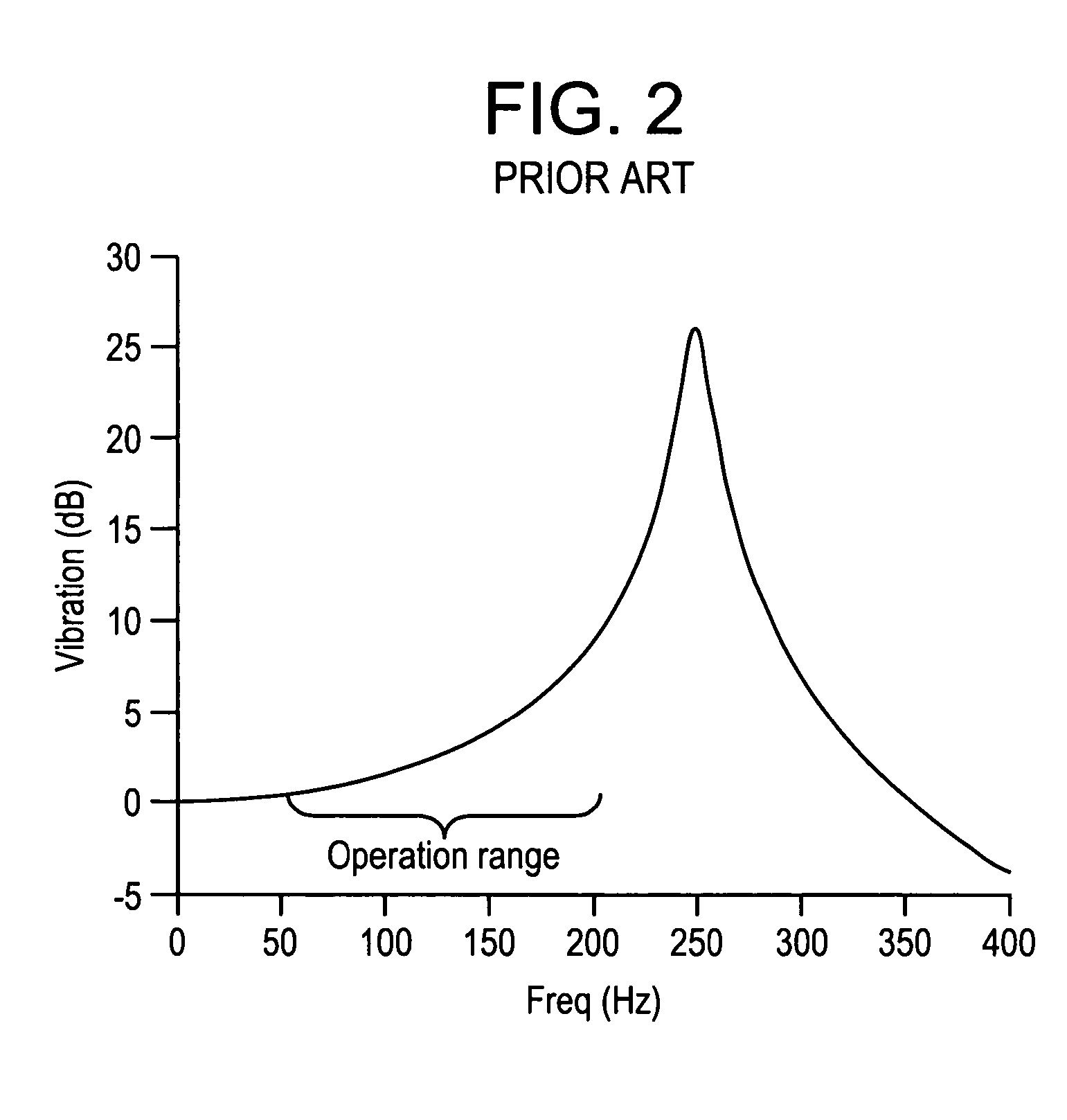
[0019]FIG. 1 depicts a hard engine mount conventionally known, and FIG. 2 shows the transmissibility of the hard engine mount, represented as vibration (dB) v. frequency (Hz). FIG. 3 depicts an engine mount 300 having an active element according to an embodiment of the present invention, while FIG. 5 depicts an engine mount according to an embodiment of the present invention, including a representation of a control system for the engine mount. FIG. 4 depicts the transmissibility (vibration v. frequency) of various engine mount configurations and methods. FIGS. 6 and 7 depict simplified representations of an engine mount to a fuselage and wing, respectively, according to embodiments of the present invention.

[0020]Turning now to FIG. 1, a conventional hard engine mount structure 100 is represented as a single degree ...


PUM


Abstract

An engine mount structure is provided with active vibration mechanisms which are attached in the vicinity of the engine mount to prevent engine vibrations from propagating into the engine mounting structure, for example, the wing or fuselage structure of an aircraft. Additionally, sensors are provided on the engine and / or wing / fuselage structure to provide control signals to the active vibration mechanisms so that the active vibration mechanism react to the sensed data to minimize the vibration transmissibility from the engine into the wing / fuselage.

Description

BACKGROUND OF THE INVENTION[0001]This invention relates to an apparatus and method for providing active vibration isolation at an engine mount to prevent engine vibration from propagating from an aircraft engine into the wings and fuselage of an aircraft.[0002]In aircraft cabins, tonal noise is generated by the fundamental frequencies of engine rotations. The generation of this noise has been an issue for many years. The tonal noise is caused by residual imbalances in the engines rotating parts, such as low and high speed turbines, fan blades, compressors, etc. Even though the imbalance from rotating parts, including shafts and blades, are closely controlled in manufacturing, due to improved manufacturing methods, the imbalance can still develop due to changes in operation, or through deterioration of the system over time. As a result, significant “once-per-revolution” vibration excitations from the rotating components are introduced into engine operations.[0003]It is these kinds of...

Claims


Application Information

Patent Timeline
Patent Type & Authority Patents(United States)
IPC IPC(8): B64D27/00
CPCB64D27/00F16F15/02F16F15/005B64C2220/00F16F15/022G05D19/02
Inventor LUO, HUAGENGYOUNG, CRAIG DOUGLAS
Owner GENERAL ELECTRIC CO
Why Eureka
Try Eureka