Holding and turning device for touch-sensitive flat objects

a technology for turning devices and flat objects, which is applied in the direction of work holders, hoisting equipment, manufacturing tools, etc., can solve the problems of inability to apply large torques, inability to provide an adequate rotational velocity, and inability to adjust the rotational velocity of the driv

Active Publication Date: 2013-05-21
ONTO INNOVATION INC
View PDF18 Cites 16 Cited by
  • Summary
  • Abstract
  • Description
  • Claims
  • Application Information

AI Technical Summary

Benefits of technology

[0015]In this way, the rotating part, namely, the lateral positioning device along with the rotational drive, can be simple in design and the moving masses can be kept low. The distance positioning device is stationary relative to it and thus can be adapted with allowance for the aerodynamical conditions quite easily to the available space, especially in consideration of the space needed for the scattered light inspection. Because the lateral positioning device does not touch the object either on its top side or its bottom side, but only in its marginal region, and because the distance positioning device has means for holding the object without involving contact, the danger of contamination of the top and bottom side of the object or wafer is minimized. The object does not have to lie by its flat surfaces on or against a part of the holding device either to ensure the desired distance or for lateral positioning or applying of a driving force.
[0019]Such distance positioning devices are also familiar, as mentioned in the introduction, but only for use in technological processes in which horizontal and vertical transporting, warehousing, or temporary storing is required. The use in connection with a rotation, especially for the inspection of the object, is not known. The benefits of this kind of distance positioning lie in a lower consumption of air and energy and consequently easier keeping clean of the air.
[0021]It has been found, especially in comparison to a nozzle arrangement with no evacuation means, that the evacuation means make it possible to lower the volume flow of fluid as well as its flow velocity, which lessens the danger of contamination. In combination with the sound generating means, the additional evacuation means have proven to be beneficial, since such a device is suitable for overhead supporting of the object and distance positioning, so that the wafer's back side can be inspected without having to turn the wafer over.
[0027]This is advantageous, because otherwise the holding device is mechanically over-determined with respect to the holding force in the distance direction, i.e., perpendicular to the object plane, so that if the axis of rotation is not oriented perfectly perpendicular to the object plane alternating forces may attack the object and can cause it to vibrate or produce particles by abrasion.

Problems solved by technology

A deformation or vibration of the wafer would result in an impairment of the measurement result in the optical sensing method.
The problem here is that pressing force is limited by the gravity acting on the wafer and therefore large torques cannot be applied.
Thus, this type of drive does not provide an adequate rotational velocity.
Another problem can be abrasion caused by the direct contact between the moving frictional rollers and the edge of the wafer.
Furthermore, this holding device can only be used in a narrow range of rpm, because an air pressure gradient is formed above a turntable of the holding device, due to the centrifugal force, and it can warp the wafer.
The aforementioned prior art is not and cannot be associated with a rotational drive in some respects, and in others can only be so associated with great expense.
In particular, the distance positioning devices which work by means of fluid flow have the drawback that the supply and drain lines for the fluid require a large construction expense and constitute large moving masses.
Such holding devices are therefore unsuited in particular for compact inspection gear that can be integrated into process machinery.
Furthermore, they have the drawback that access to the back side of the wafer for scattered light inspection is difficult owing to their construction.

Method used


Image

  • Holding and turning device for touch-sensitive flat objects
  • Holding and turning device for touch-sensitive flat objects
  • Holding and turning device for touch-sensitive flat objects

Examples


Embodiment Construction

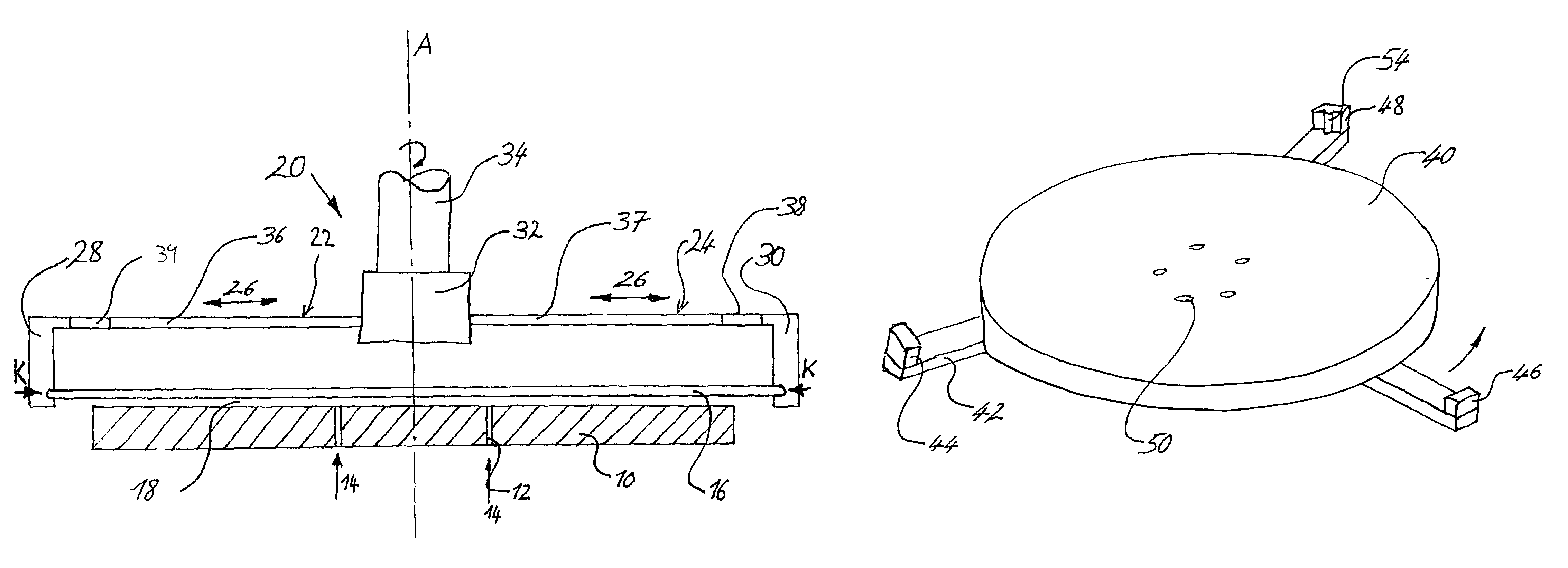
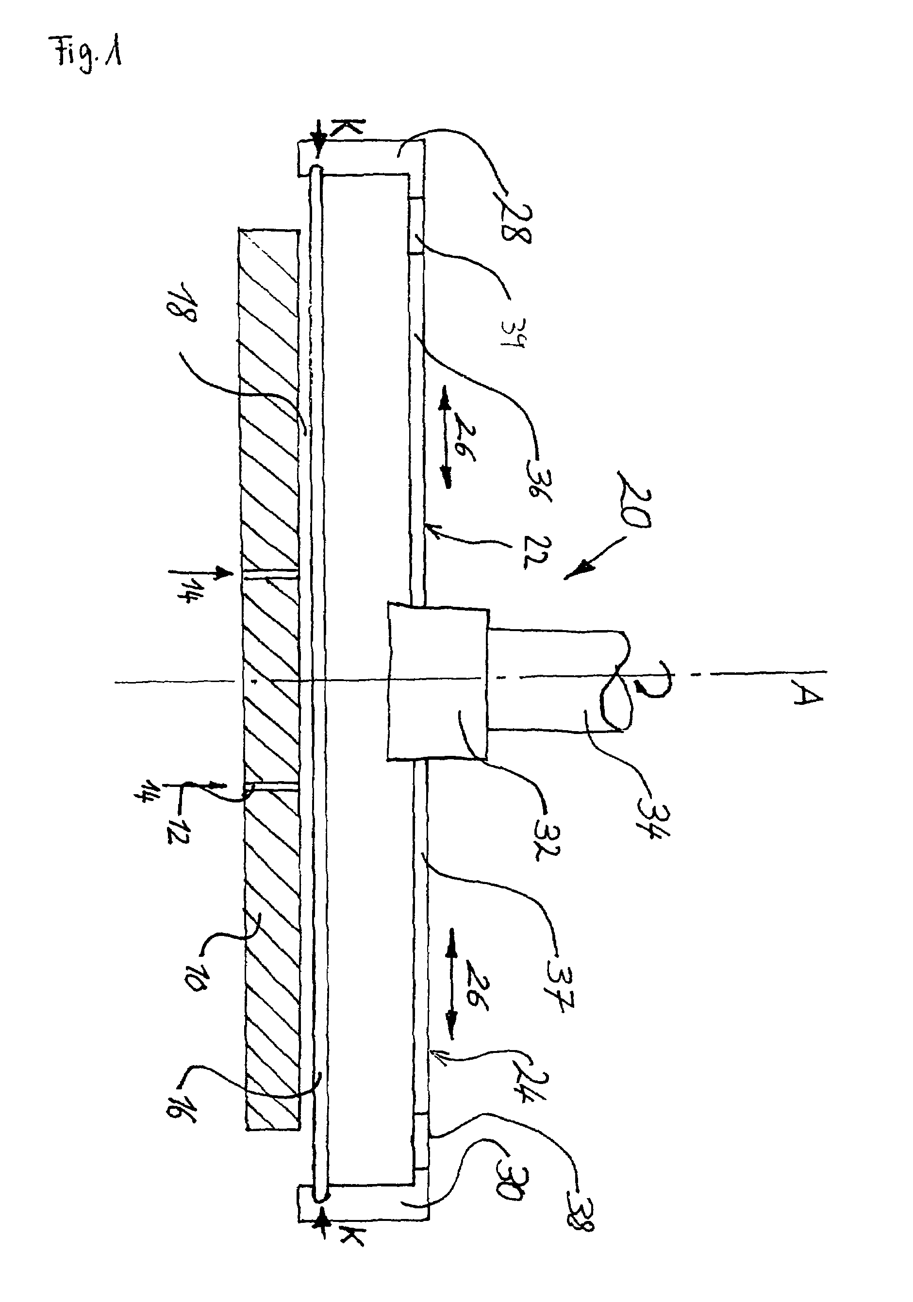
[0036]The holding device per FIG. 1 is shown partly in side view and partly in cross section. It has on its bottom side a distance positioning device in the form of a table 10 with an annular arrangement of several nozzles 12. The nozzles 12 are essentially formed by continuous bores through the table 10, which (as shown) can be arranged vertically or also at a slant to the plane of the table. The fluid flow created in this way (indicated by arrows 14) is accordingly oriented basically vertical, or possibly slanted, relative to the plane of a wafer 16 being held at a defined distance above the table; in addition, a lateral force can be exerted on the wafer by a slanted fluid flow.

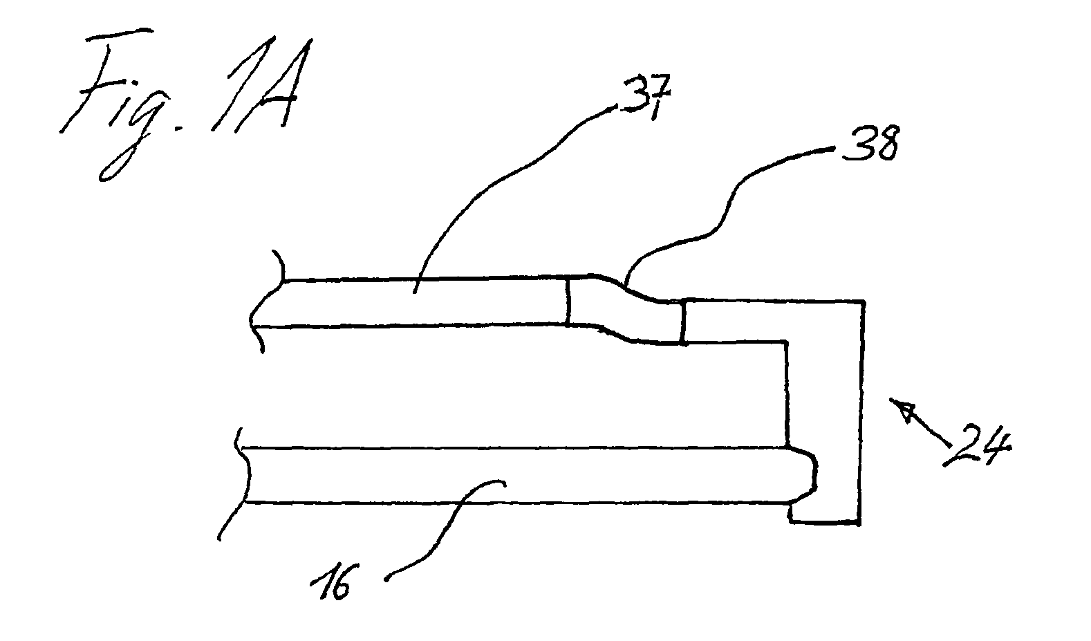
[0037]At the top side of the wafer 16 there is a lateral positioning device 20. This has three edge grippers 22, 24 arranged in the form of a spoked star with spoke segments 36, 37 running parallel to the wafer plane, only two of them being shown for simplicity. The edge grippers 22, 24 can move back and fo...


PUM


Abstract

A holding / turning device for touch-sensitive flat objects, in particular wafers, with a distance positioning device which is arranged for holding the object perpendicular to the object plane at a defined distance, a lateral positioning device, arranged for positioning the object in the object plane and for rotating together with the object about a rotational axis perpendicular to the object plane, and with a rotational drive, coupled with the lateral positioning device, providing a driving force for rotating the object about the rotational axis, wherein the driving force can be applied to the object by the lateral positioning device. The distance positioning device is adapted for holding the object without involving contact, and is decoupled from the rotational drive in such a way that the distance positioning device does not rotate together with the object.

Description

FIELD OF THE INVENTION[0001]The invention concerns a holding and turning device for touch-sensitive objects, in particular, wafers, with a distance positioning device which is arranged for holding the object perpendicular to the object plane at a defined distance, a lateral positioning device, arranged for positioning the object in the object plane and for rotating together with the object about a rotational axis perpendicular to the object plane, and with a rotational drive, coupled with the lateral positioning device, providing a driving force for rotating the object about the rotational axis, wherein the driving force can be applied to the object by means of the lateral positioning device.BACKGROUND OF THE INVENTION[0002]Wafers are automatically moved by robots both in the fabrication and during the process inspection. Some fabrication and process steps require the rotation of the wafers about their own axis. One example is the inspection of the wafers for contamination and damag...

Claims


Application Information

Patent Timeline
Patent Type & Authority Patents(United States)
IPC IPC(8): B25B11/00
CPCH01L21/68H01L21/6838H01L21/68728
Inventor SIEBERT, SONKEDREWS, DIETRICHWENZ, HOLGER
Owner ONTO INNOVATION INC
Why Eureka
Try Eureka