LED lighting device

a technology of led lighting and led modules, which is applied in the direction of lighting and heating equipment, lighting support devices, fixed installations, etc., can solve the problems of poor flexibility, uneconomical assembling of conventional led lighting devices, and inconvenient use, and achieve the effects of improving flexibility and economics for assembling led lighting devices, reducing the quantity of led modules, and small areas

Inactive Publication Date: 2013-05-21
LIN RONG GUI
View PDF4 Cites 6 Cited by
  • Summary
  • Abstract
  • Description
  • Claims
  • Application Information

AI Technical Summary

Benefits of technology

[0010]The characteristic of the present invention is that the LED lighting device includes LED modules and a plurality of heatsinks having relatively smaller areas than conventional designs, and each of the heatsinks is connected with an independent power supply having a relatively smaller power corresponding to the smaller LED module. The total areas of the LED modules and heatsinks can be expanded or contracted depending on the requirement of brightness of illumination, and the LED modules and the heatsinks are then assembled with a lamp case. Because the quantities of the LED modules, heatsinks and power supplies can be increased or reduced to adjust the brightness of the illumination, the flexibility and economy for assembling the LED lighting device can be enhanced. When some of the LED chips or part of the other electronic components is in failure and needs replacement, it only needs to have the failure parts replaced instead of having to replace all of the LED modules or all of the electronic components.

Problems solved by technology

If it needs to increase or reduce the brightness of illumination, the LED module, the heatsink and the power supply have to be replaced all together, which results in poor flexibility and is not economical for assembling the conventional LED lighting device.
When some of the LED chips or part of the other electronic components of the LED module are in failure and need replacement, the conventional LED lighting device can not replace the failure part only and has to replace the entire LED module, which is not economical.
When some of the LED chips or part of the other electronic components is in failure and needs replacement, it only needs to have the failure parts replaced instead of having to replace all of the LED modules or all of the electronic components.
When one of the LED light units is in failure, it only needs to replace the failure LED light unit.

Method used


Image

  • LED lighting device
  • LED lighting device
  • LED lighting device

Examples


Embodiment Construction

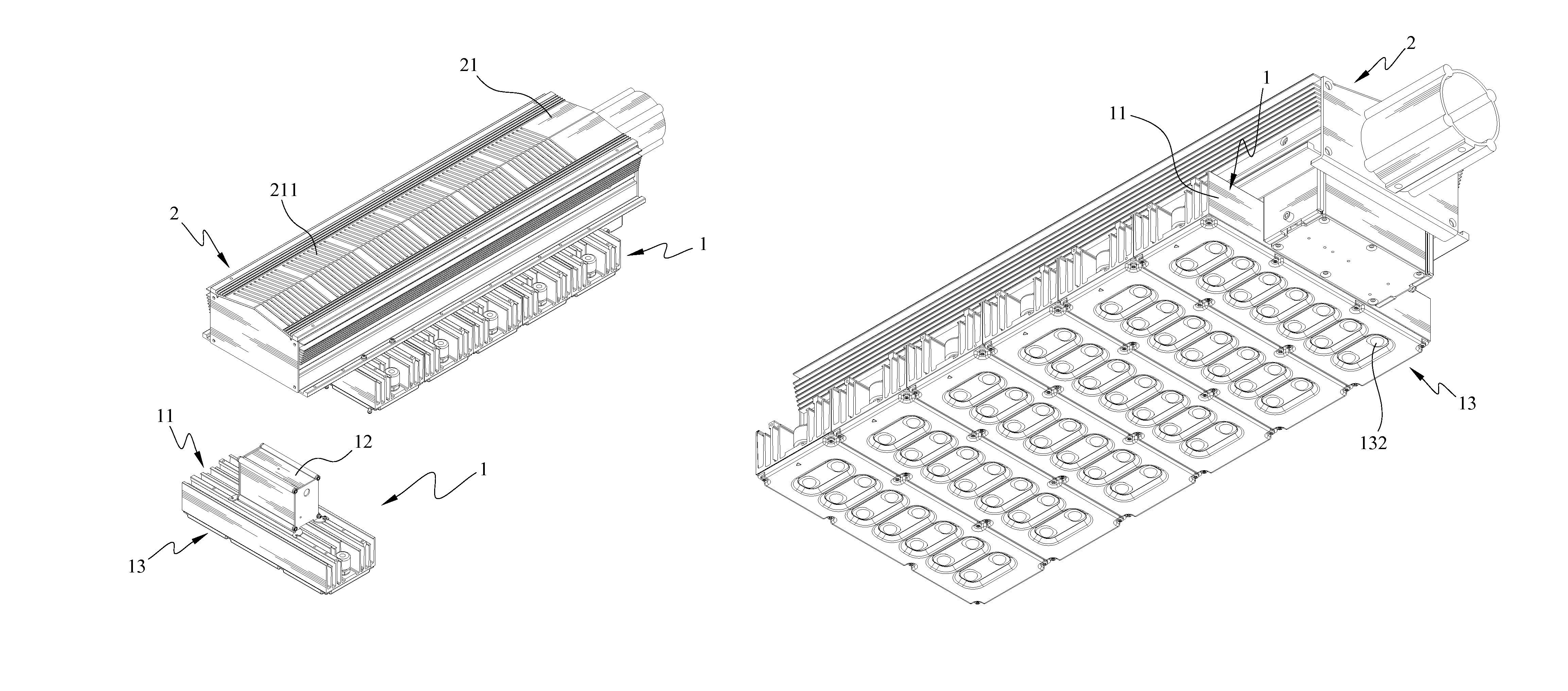
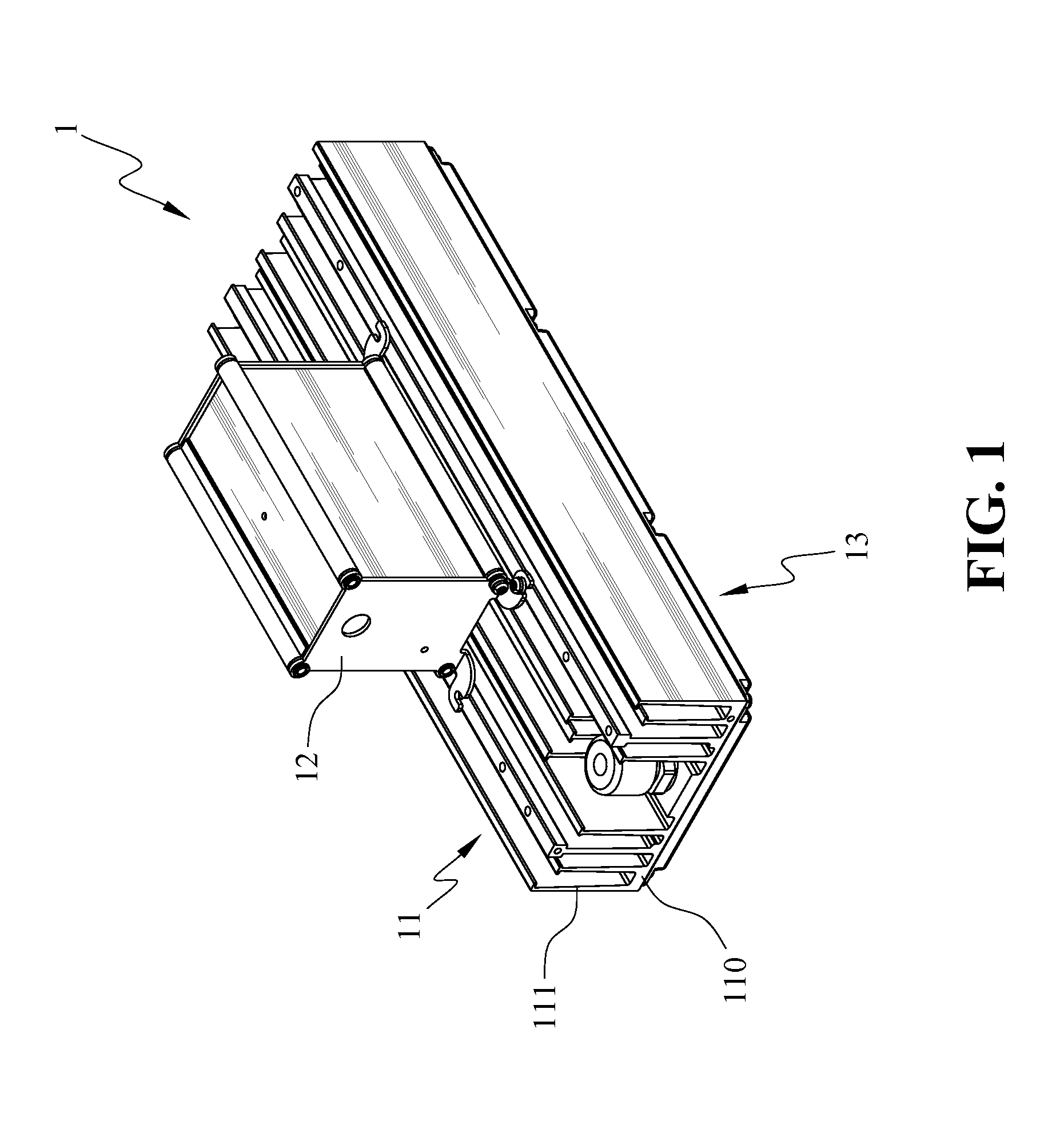
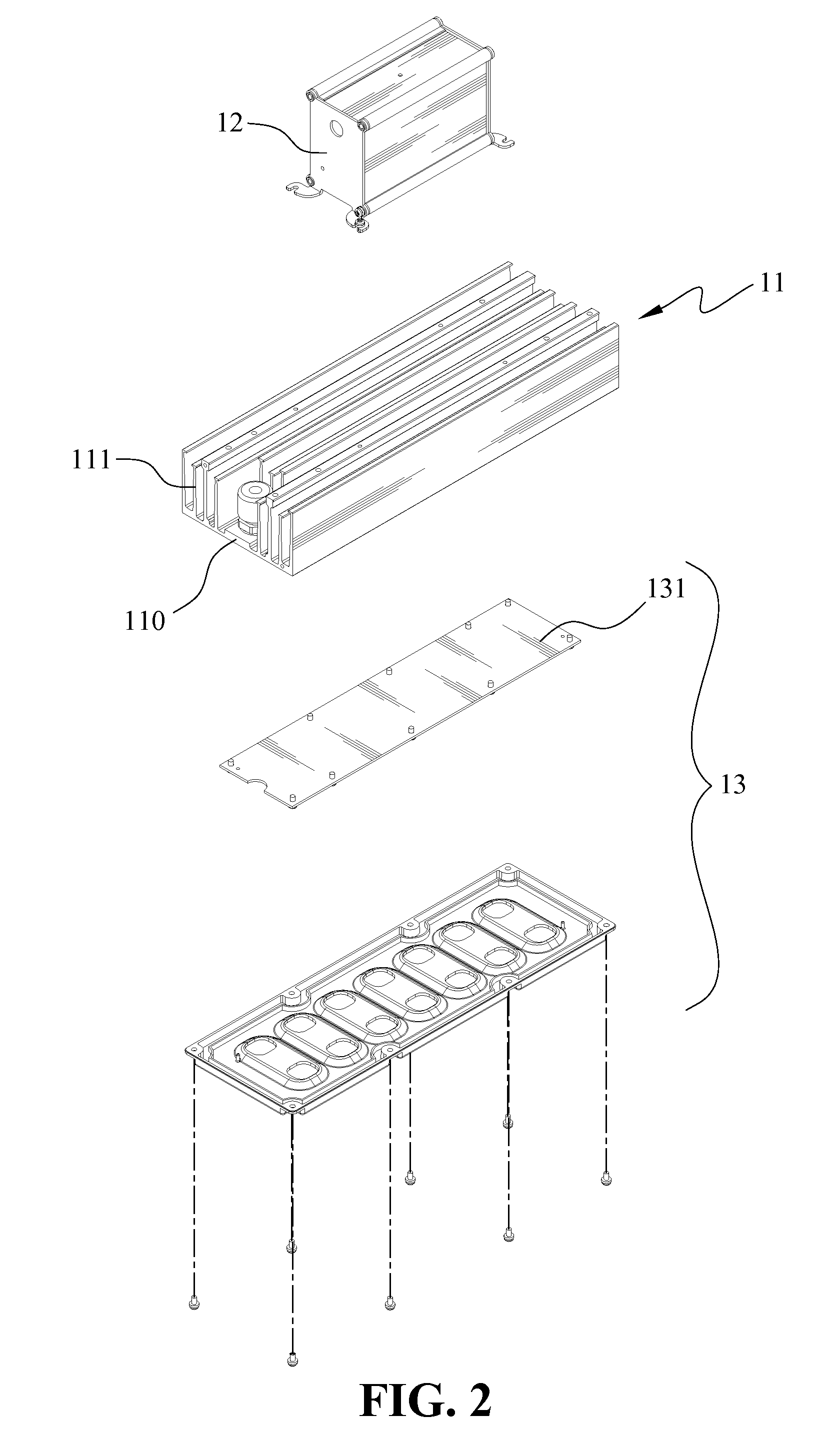
[0019]FIG. 1 is a perspective view showing a LED light unit 1 according to the present invention and FIG. 2 is an exploded view showing the LED light unit 1 according to the present invention. As shown in FIGS. 1 and 2, the LED light unit 1 comprises a heatsink 11, a power supply 12 and a LED module 13. The heatsink 11 includes a base 110 and a plurality of fins 111 connected with the base 110. The base 110 and the fins 111 of the heatsink 11 may be integrally formed in one piece by extrusion. The LED module 13 comprises a circuit board 131 and a plurality of LEDs 132 mounted on the circuit board 131. The quantity of the LEDs 132 is determined by the brightness of illumination of unit area. The circuit board 131 is mounted onto the base 110 of the heatsink 11. Thereby, the heat produced by the illuminating LEDs 132 is conducted to the fins 111 through the base 110. The heat is then carried away by air flow to the exterior environment. Otherwise, a fan (not shown in drawings) may be ...


PUM


Abstract

A light emitting diode (LED) lighting device includes a light case, a plurality of heatsinks, a plurality of LED modules and a plurality of power supplies. Each of the heatsinks is connected with one of the LED modules and one of the power supplies correspondingly to form one LED light unit. The LED light units are assembled with the light case to form the LED lighting device.

Description

BACKGROUND OF THE INVENTION[0001]1. Field of the Invention[0002]The present invention relates to a LED light for illumination and more particularly to a LED lighting device which can be assembled with more or less units based on the requirement of brightness of the illumination and part of the components can be replaced when the LED lighting device is out of order.[0003]2. The Prior Arts[0004]The light emitting diode (LED) is becoming more popular for applying in illuminating purpose because of its characteristics of smaller size, lower energy consumption and longer lifetime than conventional lighting devices, as well as the remarkable technique advance in the brightness of illumination. Because of the small size of LED, the lumen of a single LED is still lower than that of an incandescent bulb, a fluorescent lamp or conventional lamps. Therefore, the LED lighting device presently on the market is usually a LED module composed of a plurality of LEDs. The light is concentrated from t...

Claims


Application Information

Patent Timeline
Patent Type & Authority Patents(United States)
IPC IPC(8): F21V21/00F21V29/00
CPCF21V19/045F21V23/007F21V23/023F21V29/763F21V29/004F21S2/005F21W2131/103F21Y2101/02F21Y2105/001F21V19/04F21K9/20F21Y2105/10F21Y2115/10
Inventor LIN, RONG GUICHIANG, CHIH HUIWU, CHIN LI
Owner LIN RONG GUI
Why Eureka
Try Eureka