Mounting/assembly element for assembling workpieces, particularly overlapping plates and/or components

a technology for assembling workpieces and components, applied in the direction of fastening means, screws, dowels, etc., can solve the problems of nut, nut, nut, unable to withstand the turning moment, and not being able to establish sufficient resisting moment, etc., to achieve a tighter nut and stable fastening

Active Publication Date: 2013-05-21
HN3D HLDG
View PDF22 Cites 4 Cited by
  • Summary
  • Abstract
  • Description
  • Claims
  • Application Information

AI Technical Summary

Benefits of technology

[0010]It is the object of the invention to provide a mounting / assembly element of the type described above which makes possible a harder tightening of the nut on the threaded part of the rivet bush, and therewith a more stable fastening, and which also allows the use of locking fluids, without the anchored part of the rivet bush turning around during dismounting of the nut.
[0013]The possibility is achieved for insertion of a tool in that part of the rivet bush where its outer side comprises a thread and nut, so that the tool can be used as counter-hold for neutralizing the torsion moment on the rivet bush during dismounting of the nut. The insertion end of the tool is adapted to the internal non-circular cross-section of the rivet bush, and therefore, can be a special tool for safeguarding against unauthorized dismounting of the nut. Moreover, the element allows itself to be mounted with the use of a traction tool, for example, commonly-known drawing pliers, thereby enabling the implementation of a quick mounting of the element. The quick mounting can be made further effective with use of robot tools comprising the necessary traction tool, the fastening element being mounted as an insertion part which is introduced through two overlapping holes in the items being connected. The draw rod is influenced by traction for deformation of the deformable part of the rivet bush until breakage, so that the remaining part of the draw-rod connected with the draw-head will be localized in the deformable zone of the rivet bush, or alternatively, in the lower end of the threaded end of the rivet bush, so that there is room for introduction of an insertion tool cooperating with the non-cylindrical inside cross-section for establishing of counter-hold in connection with the dismounting and mounting of the nut.
[0017]With the object of ensuring a quick insertion of the assembly element in connection with use, the free end of the draw-head can have a pointed, conical extent. There is hereby achieved a quick centering and introduction of an assembly element in overlapping holes in items which are to be joined together with the assembly element.
[0020]With the object of ensuring a better friction between the outer side of the rivet bush and the facing side of the item, the outside surface of the rivet bush's deformation zone can be grooved. In the fastening of the rivet bush, the grooving will grip more firmly in the facing side of the item, which will counteract rotation of the rivet bush along with the nut during the dismounting of the nut. Moreover, the rivet bush will hereby also better withstand vibrations.
[0024]With the object of providing good engagement facilities for the draw tool which is used for the fastening of the assembly element, the outside surface of the draw-rod, in the end opposite the break zone, can comprise grooving or corrugations. The possibility is thereby achieved of establishing a better grip as a result of the greater friction between the elements of the draw tool and the draw-rod.

Problems solved by technology

However, the fastening element disclosed in German Patent Application DE 39 02 226 A1 has the weakness that the rivet bush, in the dismounting and mounting of the nut, can sometimes not withstand the turning moment which is applied to the nut, in that the rivet bush simply turns around with the nut when the turning moment exceeds the frictional force which is established by the fastening of the rivet bush in a relevant hole in the construction in which the mounting element forms part.
This, however, has proved to be inadequate, and in the use of said known mounting element, it has thus not been possible to establish sufficient resisting moment to be able to dismount and remount the nut on the element without the rivet bush turning around in its seating in the lowermost construction part.
Also, the mounting element has not found application with more strength-demanding fastenings.
Moreover, the mounting element will not be suitable for fastening / mounting of parts on locations where vibrations arise, e.g., on machine parts where use is sometimes made of locking fluid to ensure that the nut remains in the preferred position.
Other things being equal, this will involve a slow, time-consuming and difficult mounting procedure for the mounting element, which will hardly be attractive with the demands for efficiency which are made today in connection with the assembly of construction elements.
Moreover, said mounting elements hardly find application in connection with an automated assembly of construction elements, for example in connection with assembly robots.

Method used


Image

  • Mounting/assembly element for assembling workpieces, particularly overlapping plates and/or components
  • Mounting/assembly element for assembling workpieces, particularly overlapping plates and/or components
  • Mounting/assembly element for assembling workpieces, particularly overlapping plates and/or components

Examples


Embodiment Construction

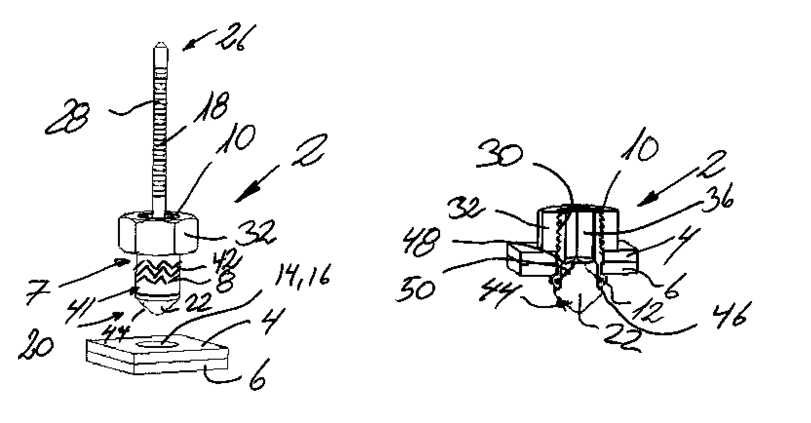
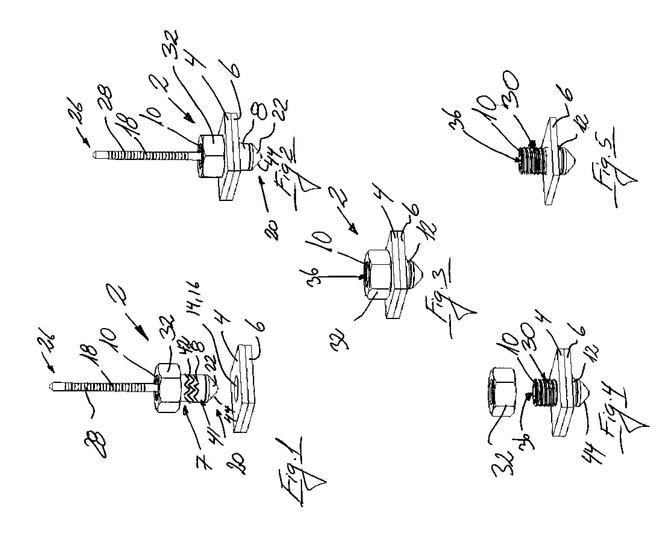
[0039]In FIG. 1, a first embodiment of the mounting / assembly element 2 for use in the assembly of items, particularly overlapping plate parts 4, 6, and components, is shown.

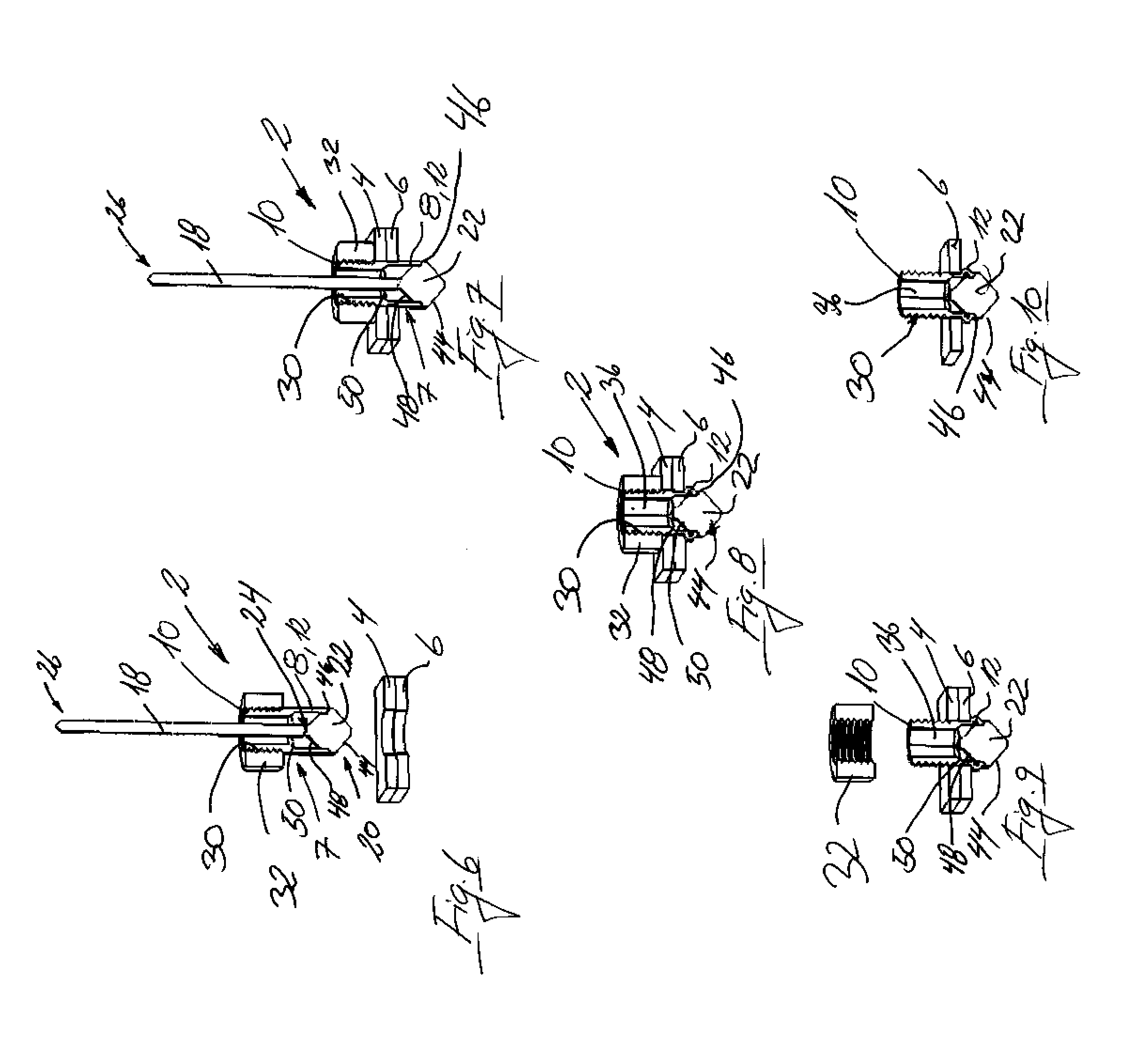
[0040]The mounting / assembly element 2 comprises a rivet bush 7 with a first end 8 and a second end 10. As is shown more clearly in FIGS. 6-10, the first end 8 comprises a deformable zone 12 for insertion through coincident holes 14, 16 in the items 4, 6, and in the rivet bush 7, there is housed a draw-rod 18, the first end 20 of which comprises a draw-head 22 with a greater diameter than the draw-rod 18 and a break zone 24 above the draw-head 22.

[0041]The draw-head 22 is housed in the deformable zone 8, 12 of the rivet bush. The second end 26 of the draw-rod 18 extends up out of the second end 10 of the rivet bush 7, and in the illustrated embodiment, comprises a corrugation 28 which serves to provide a better grip for the draw tool which is used for the mounting / fastening of the element 2 in the lowermost plate ...


PUM


Abstract

A mounting / assembly element rivet bush having a deformable first end for insert through items to be connected and a second end for mounting a nut. A draw tool having a break zone is located in the first end of the rivet bush, and the second end of the rivet bush is provided with a non-cylindrical internal cross section which cooperates with an insertion tool, such as an Allen wrench. When the mounting / assembly element is held fast in the items to be connected, the part of the break zone of the draw tool for the deformation of the rivet bush is lying in the deformable first end of the rivet bush. A counter-hold for torsion forces which arise with the dismounting and remounting of the nut is produced with the insertion tool thereby achieving a considerably greater tightening effect and also ensuring that the mounting / assembly element can be reused.

Description

BACKGROUND OF THE INVENTION[0001]1. Field of Invention[0002]The present invention relates to a mounting / assembly element for use in the assembly of items, particularly overlapping plate parts and / or components, and comprising a rivet bush with a first end and a second end, and where the first end comprises a deformable zone for insertion through holes lying over each other in the items, and where there is housed a draw-rod in the rivet bush, the first end of which comprises a draw-head with a larger diameter than the draw-rod and a break zone above the draw-head which is housed in the deformable zone of the rivet bush, and where the second end of which extends up over the second end of the rivet bush, and where the second end of the rivet bush comprises an external thread on which there is provided a cooperating nut, said mounting / assembly element being intended for fastening by use of a drawing tool engaged in the draw-rod for breakage in the break zone.[0003]2. Description of Rela...

Claims


Application Information

Patent Timeline
Patent Type & Authority Patents(United States)
IPC IPC(8): F16B13/04
CPCF16B37/062F16B19/1054F16B5/02F16B5/04F16B19/10F16B37/06
Inventor NIELSEN, HANS
Owner HN3D HLDG
Why Eureka
Try Eureka