Gear apparatus for a centrifuge including a drive shaft having two hollow longitudinal channels for lubricating the gear apparatus via an associated lubricant compensating system

a technology of gear apparatus and longitudinal channel, which is applied in the direction of centrifuges, bearing components, gear details, etc., can solve the problems of affecting the centrifuge operation, oil running out of the container, and it is not readily possible to check the filling level or add more gear oil

Active Publication Date: 2013-05-21
GEA MECHANICAL EQUIP
View PDF14 Cites 4 Cited by
  • Summary
  • Abstract
  • Description
  • Claims
  • Application Information

AI Technical Summary

Benefits of technology

[0009]In order to compensate for any losses of oil and in order to promptly obtain during operation an indication of an existing leak, an oil compensating container is installed above the gear apparatus. The oil compensating container is connected to the oil volume in the gear via a rotary lead-in, the transfer point being located axially and centrally on the drive shaft of the gear. If oil is lost in the gear, oil can run out of the container into the gear. Damage is thus prevented in a simple manner.
[0010]In addition, the gear apparatus of the present disclosure avoids differences in pressure or prevents pressure from building up in the gear apparatus during heating in a manner that might lead to “breathing” and possibly the infiltration of dirt / water.
[0011]In addition, oil losses become more reliably detectable. It is thus possible to visually detect a loss of oil before the gear apparatus is jeopardized.
[0021]It is advantageous if the transverse holes are formed independently of the direction of rotation in such a way that one channel pumps and one draws in. When the housing rotates, a correspondingly designed rotary lead-through provides a defined system. That is, oil is conveyed into the gear apparatus in a targeted manner and air is conveyed out. This arrangement has a plurality of advantages.
[0023]In addition, it allows air to be brought safely out of the gear apparatus.
[0024]In addition, the solution, according to the present disclosure, can be implemented in a simple manner in designs having a secondary motor arranged on the end side for driving the screw. It is particularly suitable for lubricating the gear apparatus with oil instead of fat.

Problems solved by technology

In decanter gear apparatuses which are continuously filled with oil, it is not readily possible to check the filling level or add more gear oil during ongoing operation.
If oil is lost in the gear, oil can run out of the container into the gear.
In addition, possible contamination of the material to be centrifuged is impeded, particularly in the case of an internal gear.
Nevertheless, in an implementation of a drive concept with motors mounted on the end side and coaxially with the drive shaft, referred to as a direct drive, the concept of the central rotary lead-in is possible only with relatively great technical effort.
A further problem exists in the fact that it is not possible to reliably rule out loss of oil in the gear apparatus.

Method used


Image

  • Gear apparatus for a centrifuge including a drive shaft having two hollow longitudinal channels for lubricating the gear apparatus via an associated lubricant compensating system
  • Gear apparatus for a centrifuge including a drive shaft having two hollow longitudinal channels for lubricating the gear apparatus via an associated lubricant compensating system
  • Gear apparatus for a centrifuge including a drive shaft having two hollow longitudinal channels for lubricating the gear apparatus via an associated lubricant compensating system

Examples


Embodiment Construction

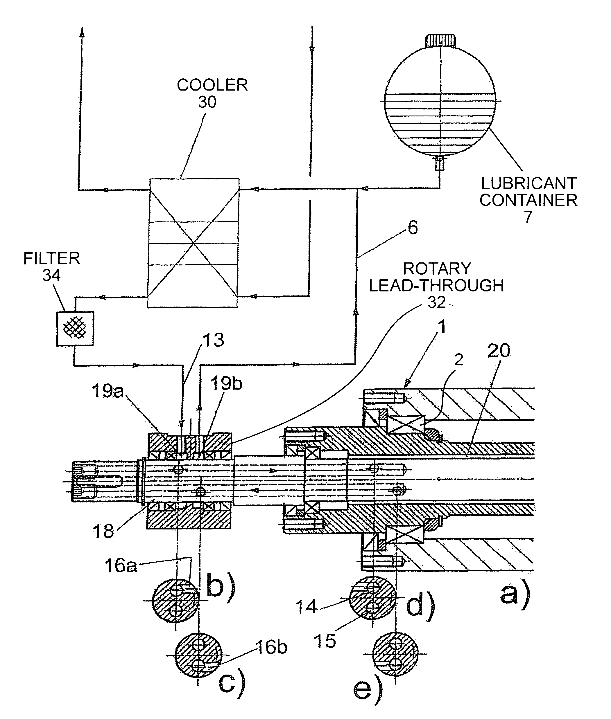
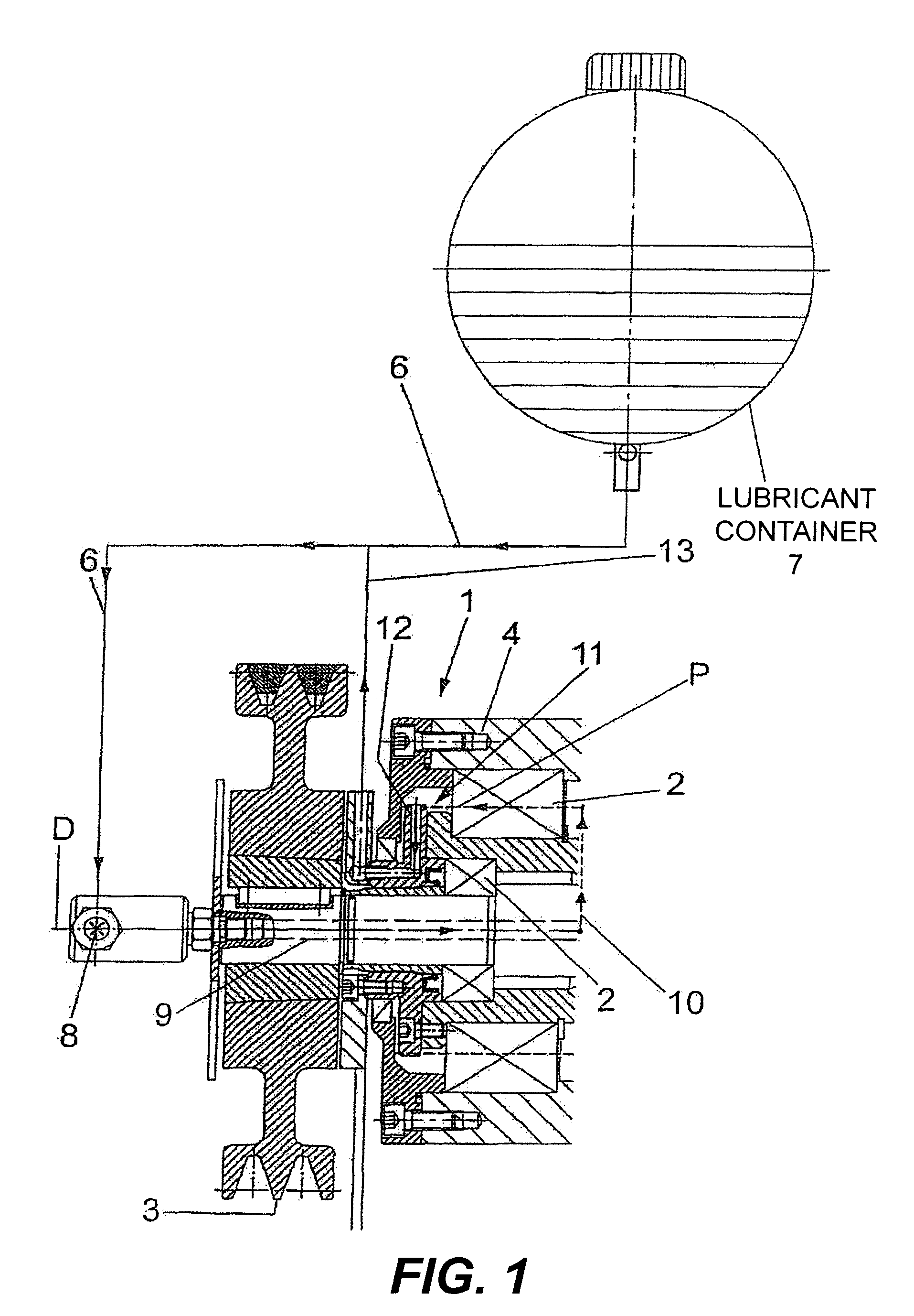
[0035]FIG. 1 is a sectional view of a gear apparatus 1 of a solid bowl screw centrifuge. With regard to the construction of such a solid bowl screw centrifuge, see, for example, FIG. 6.

[0036]The solid bowl screw centrifuge of FIG. 6 has a screw 22 and a drum 23. The gear apparatus 1 is connected between at least one or two drive motors 24, 25.

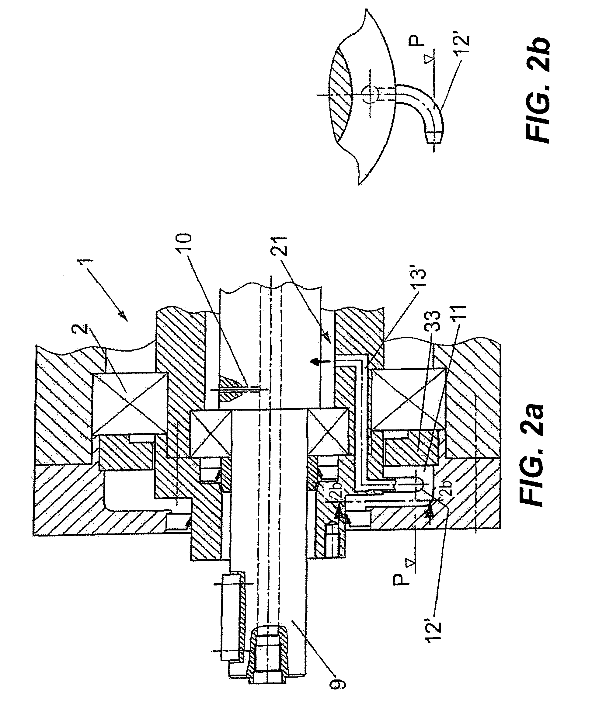
[0037]When installed, the gear apparatus 1 may be oriented in such a way that rotating parts of the gear apparatus 1 each have horizontally oriented axes of rotation. The main axis of rotation of a central drive shaft 9, 18 is denoted by D. See, for example, FIGS. 1, 3, 5 and 6. The elements to be lubricated of the gear apparatus 1 include a plurality of bearings 2.

[0038]The gear apparatus 1 is designed as a gear apparatus which is continuously filled with lubricant, such as oil. It is constructed in various manners and may have one or more gears each having at least one or more gear stages which can be designed, for example, as planetary gear ...


PUM


Abstract

A gear apparatus for a solid-bowl screw centrifuge. The gear apparatus includes a shaft, a gear, and a bearing. The centrifuge includies a drum and a screw, both of which are configured to be driven. The screw is further configured to be driven at a different rotational speed relative to the drum. The gear apparatus is connected between one or more drive motors and the screw and the drum. The gear apparatus is continuously filled with a lubricant and includes a hollow drive shaft having two hollow longitudinal channels extending in an axial direction. Also included is a lubricant compensating system having a lubricant compensating container connected via a line and a rotary lead-through for lubricating the bearing through the two hollow longitudinal channels.

Description

BACKGROUND OF THE INVENTION[0001]This application is a national stage of International Application PCT / EP2009 / 053135, filed Mar. 17, 2009 and claims benefit of and priority to German Patent Application No. 10 2008 015 134.3, filed Mar. 20, 2008, the content of which Applications are incorporated by reference herein.BACKGROUND OF THE INVENTION[0002]The present disclosure relates to a gear apparatus for a centrifuge, such as a solid bowl screw centrifuge. The solid bowl screw centrifuge includes a drum to be driven and a screw to be driven at a differential rotational speed relative to the drum. The gear apparatus is connected between at least one or more drive motors and the screw and the drum and the gear apparatus is continuously filled with an oil-type free-flowing lubricant.[0003]For driving decanters, for example, solid bowl screw centrifuges, use is made of gear apparatuses which are connected downstream of the drive motors and have elements which rotate at the rotational speed...

Claims


Application Information

Patent Timeline
Patent Type & Authority Patents(United States)
IPC IPC(8): B04B1/20F16C33/66B04B9/08
CPCB04B1/2016F16C33/6659B04B9/04Y10T74/19991
Inventor OSTKAMP, WILHELMNEUBAUER, RICHARD
Owner GEA MECHANICAL EQUIP
Why Eureka
Try Eureka