Hermetic seal leak detection apparatus

a leak detection and hermetic seal technology, applied in the direction of measurement devices, instruments, structural/machine measurement, etc., can solve the problems of large leaks, easy identification of leaks, and stable pressure readings, and achieve accurate interpretation of results, rapid stabilization, and greater control

Active Publication Date: 2013-05-28
NASA
View PDF17 Cites 20 Cited by
  • Summary
  • Abstract
  • Description
  • Claims
  • Application Information

AI Technical Summary

Benefits of technology

[0014]A vacuum tight chamber is created around the unit being tested to minimize gas space outside of the hermetic seal. A vacuum inducing device (e.g., a plunger) is then used to increase the gas volume inside the device, so that a slight vacuum is pulled on the unit being tested. The pressure in the unit being tested will stabilize. If the stabilized pressure reads close to a known good seal calibration, there is not a leak in the seal. If the stabilized pressure reads closer to a known bad seal calibration value, there is a leak in the seal. The speed of the plunger can be varied and by evaluating the resulting pressure change rates and final values, the leak rate / size can be accurately calculated.
[0017]It is important that the device is calibrated for known good and bad seals for the unit being tested in order to accurately interpret results. Calibration readings should be taken using the specific means by which the pressure differential in the vacuum tight chamber will be created. While seal leaks can be determined and measured with this device using the laws of thermodynamics including but not limited to the ideal gas laws, automating the system and performing calibrations while the device is in place in the system will provide greater control and quicker, more accurate calculations of leak size / rate.

Problems solved by technology

If the stabilized pressure reads closer to a known bad seal calibration value, there is a leak in the seal.
Large leaks are also easily identified, as a large leak will create a rapid depressurization, resulting in a rapidly stabilized pressure reading closer to the known bad seal calibration.

Method used


Image

  • Hermetic seal leak detection apparatus
  • Hermetic seal leak detection apparatus
  • Hermetic seal leak detection apparatus

Examples


Embodiment Construction

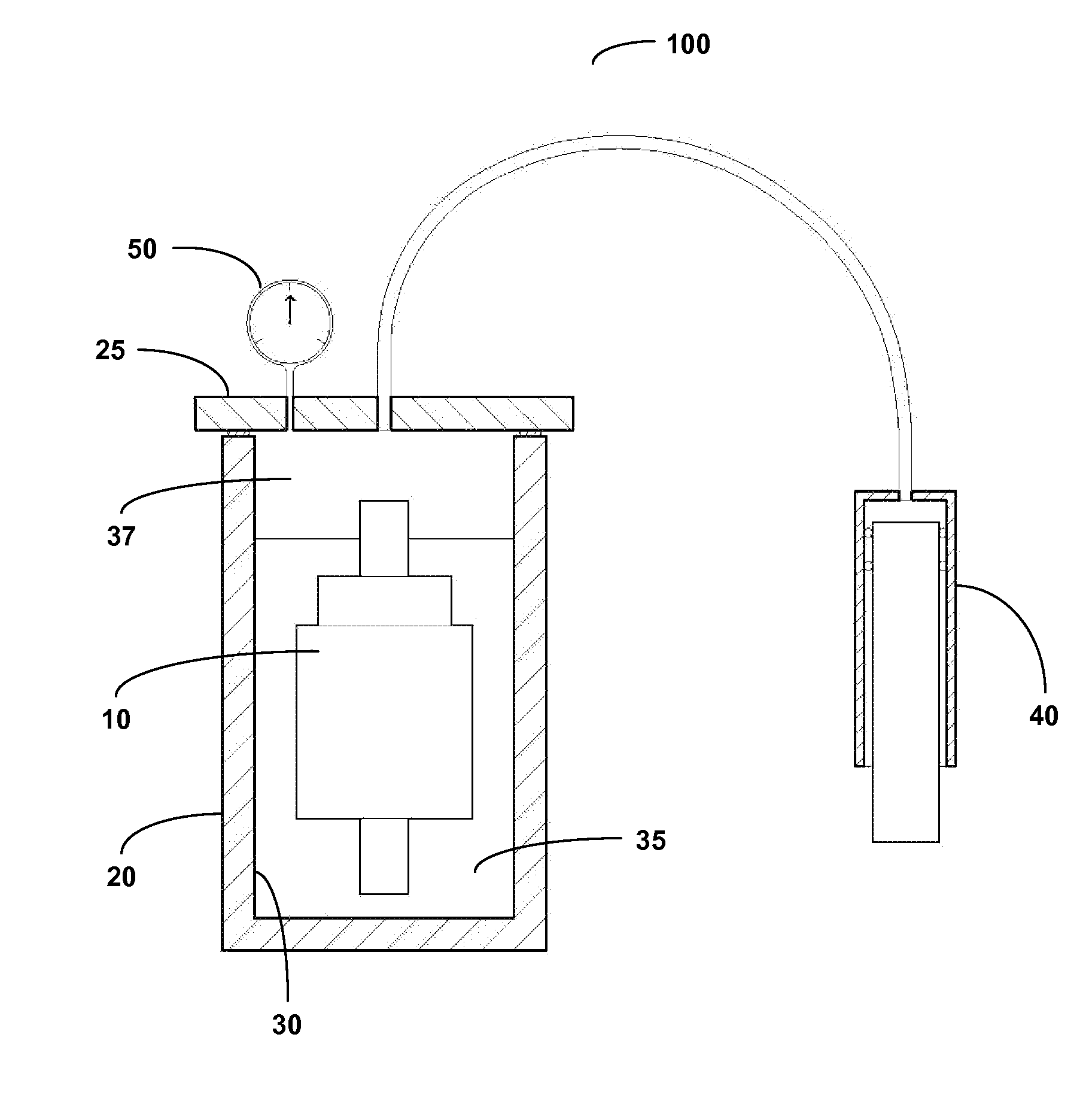
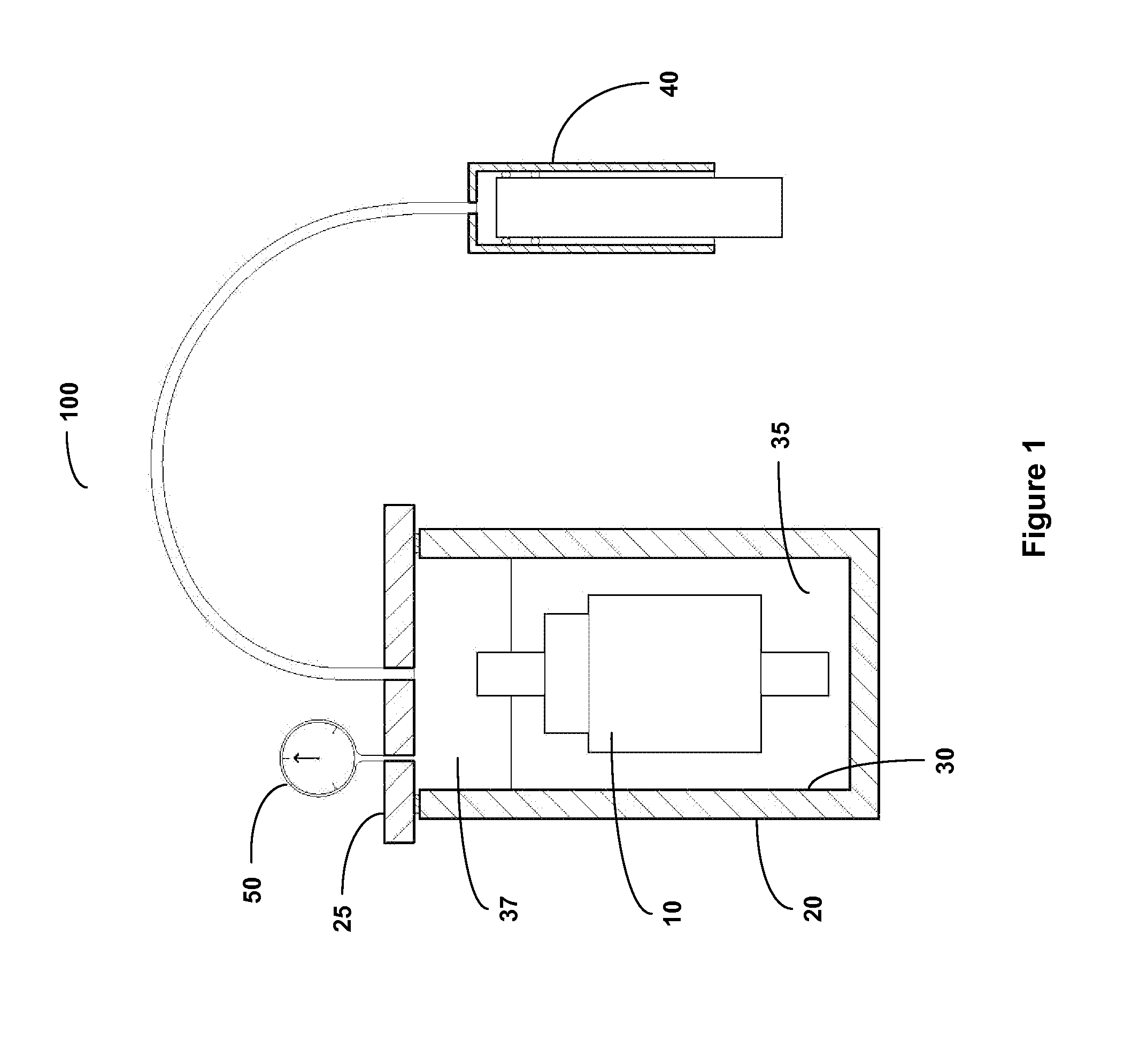
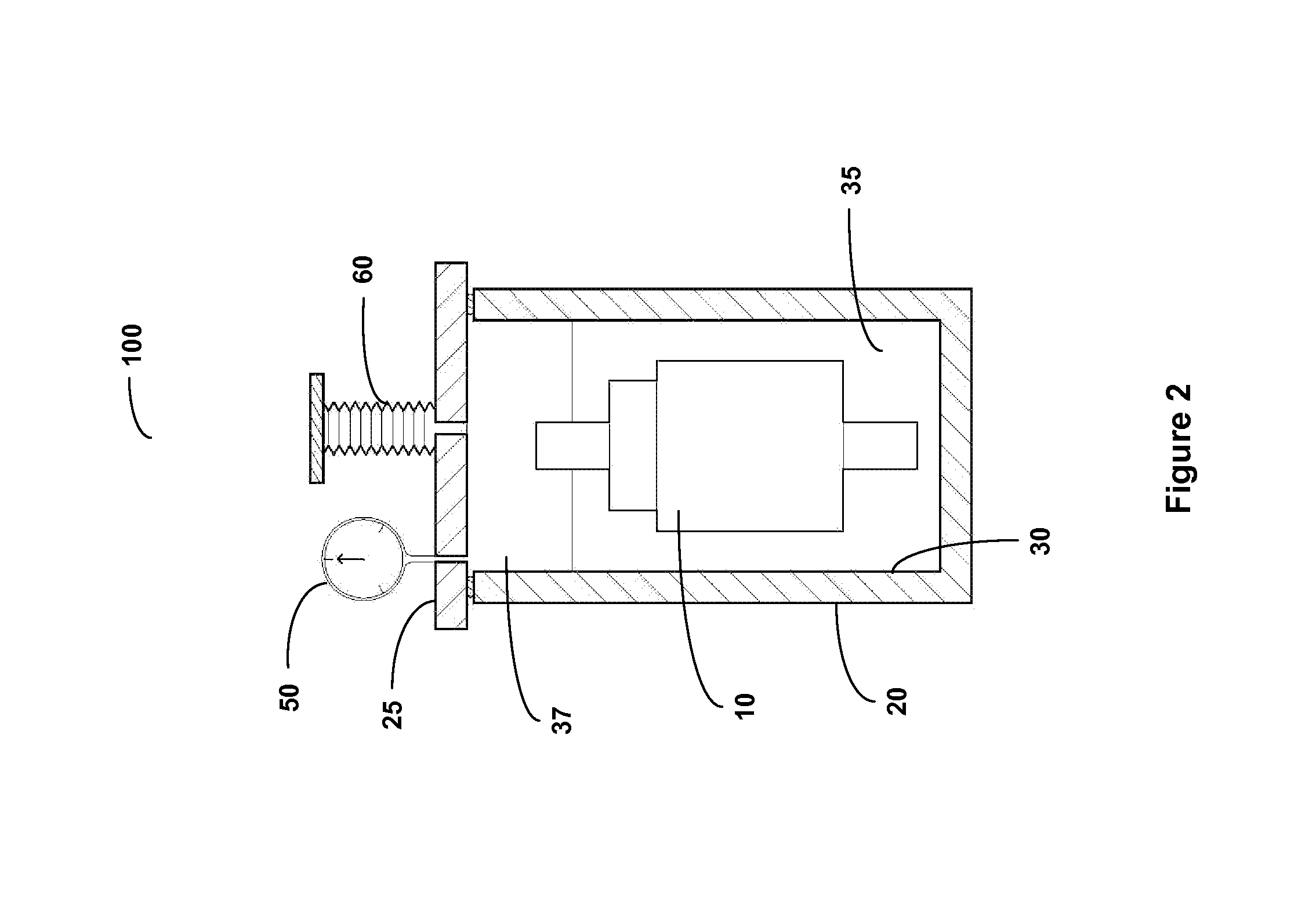
[0025]For the purpose of promoting an understanding of the present invention, references are made in the text to exemplary embodiments of a hermetic seal leak detection apparatus, only some of which are described herein. It should be understood that no limitations on the scope of the invention are intended by describing these exemplary embodiments. One of ordinary skill in the art will readily appreciate that alternate but functionally equivalent materials, components, and placement may be used. The inclusion of additional elements may be deemed readily apparent and obvious to one of ordinary skill in the art. Specific elements disclosed herein are not to be interpreted as limiting, but rather as a basis for the claims and as a representative basis for teaching one of ordinary skill in the art to employ the present invention.

[0026]It should be understood that the drawings are not necessarily to scale; instead, emphasis has been placed upon illustrating the principles of the inventio...


PUM


Abstract

The present invention is a hermetic seal leak detection apparatus, which can be used to test for hermetic seal leaks in instruments and containers. A vacuum tight chamber is created around the unit being tested to minimize gas space outside of the hermetic seal. A vacuum inducing device is then used to increase the gas chamber volume inside the device, so that a slight vacuum is pulled on the unit being tested. The pressure in the unit being tested will stabilize. If the stabilized pressure reads close to a known good seal calibration, there is not a leak in the seal. If the stabilized pressure reads closer to a known bad seal calibration value, there is a leak in the seal. The speed of the plunger can be varied and by evaluating the resulting pressure change rates and final values, the leak rate / size can be accurately calculated.

Description

FEDERAL RESEARCH STATEMENT[0001]The invention described herein was made by an employee of the United States Government and may be manufactured and used by or for the Government of the United States of America for governmental purposes without the payment of any royalties thereon or therefore.TECHNICAL DESCRIPTION OF THE INVENTION[0002]This invention relates generally to the field of testing and measuring seals for leaks, and more specifically to an apparatus designed to test hermetic seals for leaks without the need for gas pressurization, vacuum systems, mass spectrometers, and risk of gas contamination.BACKGROUND OF THE INVENTION[0003]The hermetic seal on shuttle rocket booster (SRB) pressure sensors cannot be easily tested for leaks. Currently, if a leak is suspected in one of these hermetic seals, the seal can be tested only by traditional seal leak evaluation methods, which may require disassembling the transducer or some other form of destructive testing. With SRB pressure sen...

Claims


Application Information

Patent Timeline
Patent Type & Authority Patents(United States)
IPC IPC(8): G01M3/34
CPCG01M3/329
Inventor KELLEY, ANTHONY R.
Owner NASA
Why Eureka
Try Eureka