Phase interleaving control method for a multi-channel regulator system

a regulator system and control method technology, applied in the direction of pulse technique, instruments, code conversion, etc., can solve the problems of increased circuit size and cost, system lack of flexibility, and degraded transient respons

Active Publication Date: 2013-05-28
RICHTEK TECH
View PDF3 Cites 1 Cited by
  • Summary
  • Abstract
  • Description
  • Claims
  • Application Information

AI Technical Summary

Problems solved by technology

Although increasing the decoupling capacitor Cde will help decrease the ripples in the input voltage Vin, such increase also increases the circuit size and costs, and degrades the transient response.
Since the master / slave configuration cannot be rearranged, the system is lack of flexibility.
Moreover, the master channel must always keep enabled, and the phase delay for clocks it provides for the slave channels is fixed after each setting, so that the number of the slave channels cannot be increased or decreased arbitrarily.
In other words, the amount of the channels for a multi-channel regulator system cannot be increased or decreased arbitrarily.

Method used


Image

  • Phase interleaving control method for a multi-channel regulator system
  • Phase interleaving control method for a multi-channel regulator system
  • Phase interleaving control method for a multi-channel regulator system

Examples


first embodiment

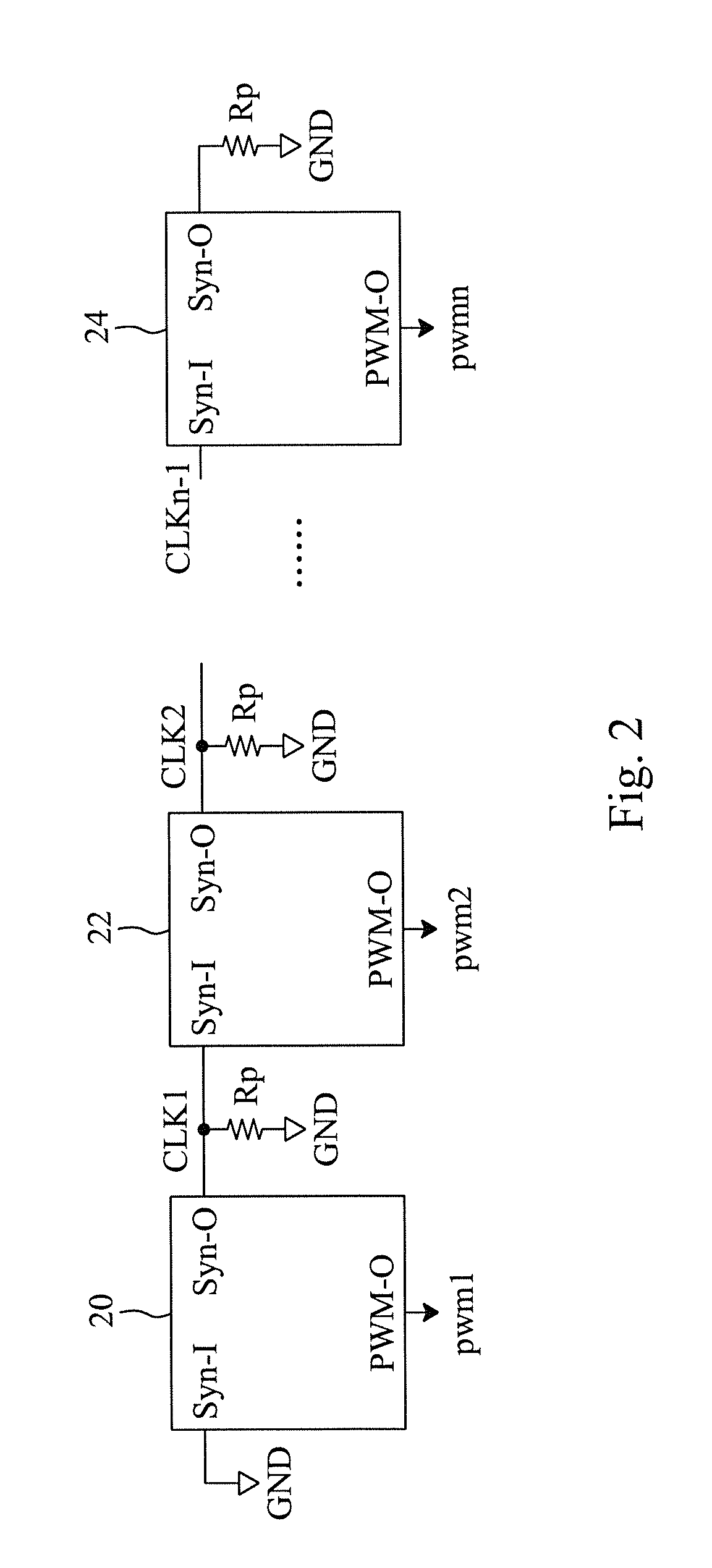
[0014]In a first embodiment according to the present invention, referring to FIG. 2, a multi-channel regulator system includes a plurality of PWM ICs 20-24 connected in series, and each of the PWM ICs 20-24 controls a channel and has an input pin Syn-I for receiving a synchronous clock, an output pin Syn-O for providing a synchronous clock, and an output pin PWM-O for providing a pulse width modulation signal. Except that the input pin Syn-I of the PWM IC 20 in the first stage is grounded, the input pin Syn-I of each of the other PWM ICs 22-24 is connected to the output pin Syn-O of its previous stage. The output pin Syn-O of each of the PWM ICs 20-24 is connected with a resistor Rp which functions as a phase setting device to set the phase of the synchronous clock provided to the next stage. Alternatively, the resistor Rp may be integrated into the PWM IC it is connected therewith. For each of the PWM ICs 20-24, since the functions of phase setting and clock outputting use a same p...

second embodiment

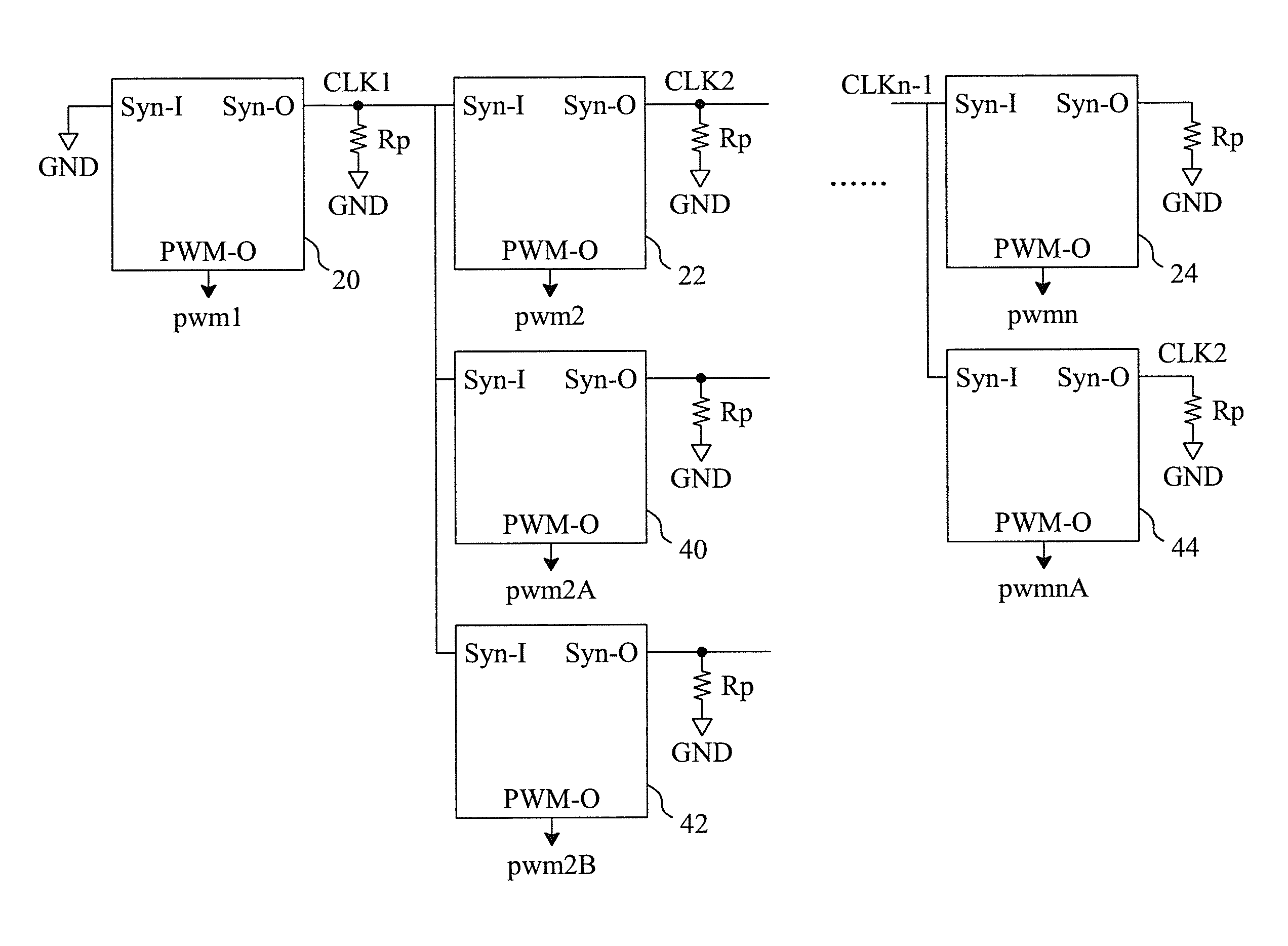
[0021]FIG. 5 is a second embodiment according to the present invention. In addition to the PWM ICs 20-24 as shown in FIG. 2, there are PWM ICs 40 and 42 connected in parallel with the PWM IC 22, and a PWM IC 44 connected in parallel with the PWM IC 24. The PWM ICs 40-44 are similar to the PWM ICs 20-24, and the control method for the PWM ICs 40-44 is similar to that illustrated in FIG. 3 and FIG. 4.


PUM


Abstract

A multi-channel regulator system includes serially connected PWM integrated circuits, each of which determines a PWM signal for a respective channel to operate therewith, and individually controls its operation mode according to whether or not an external clock is detected. Therefore, each channel will not be limited to operate under a constant mode and could become a master channel or a slave channel. Additionally, each of the PWM integrated circuits generates a phase shifted synchronous clock for its next channel during it is enabled, and thus all the channels operate in a synchronous but phase interleaving manner.

Description

FIELD OF THE INVENTION[0001]The present invention is related generally to a multi-channel regulator system and, more particularly, to a multi-channel phase interleaved regulator system.BACKGROUND OF THE INVENTION[0002]As shown in FIG. 1, a multi-channel regulator system includes a plurality of common input channels 10 for converting an input voltage Vin into a plurality of output voltages Vo1-VoN, respectively. Each channel 10 includes a pulse width modulation (PWM) integrated circuit (IC) 12 and a power stage 14, in which the PWM IC 12 generates a pulse width modulation signal pwm responsive to a synchronous clock to drive the power stage 14 to convert the voltage Vin. Since the pulse width modulation signals pwm of all the channels 10 are triggered by the same synchronous clock, all the channels 10 will simultaneously draw current from the common input power supply Vin at the moment of switching all the pulse width modulation signals pwm on, and cause greater ripples in the input ...

Claims


Application Information

Patent Timeline
Patent Type & Authority Patents(United States)
IPC IPC(8): H03K7/08
CPCH03K7/08H03K19/00346H02M2003/1586H02M3/1586
Inventor CHEN, AN-TUNGLU, SHAO-HUNGCHEN, ISAAC Y.
Owner RICHTEK TECH
Why Eureka
Try Eureka