Adjustment of acoustic properties based on proximity detection
a technology of proximity detection and acoustic properties, applied in the direction of electrical transducers, gain control, instruments, etc., can solve the problems of missing part of conversation and missing conversation, and achieve the effect of increasing the volume of air
- Summary
- Abstract
- Description
- Claims
- Application Information
AI Technical Summary
Benefits of technology
Problems solved by technology
Method used
Image
Examples
first embodiment
[0028]In a first embodiment according to the invention, shown in FIG. 4, circuitry 400 otherwise is essentially identical to circuitry 300, except that a proximity signal 401 is combined with user input 302 at combining circuits 402, so that proximity signal 401 is taken into account along with user input 302 in setting the acoustic property or properties. In this embodiment, it may not be necessary to control the audio source 301 itself, although the volume or other properties could be controlled there. Thus, audio source 301 in this embodiment could be viewed as an audio generator and adjustment circuit.
[0029]Combining circuits 402 can be implemented in different ways. For example, combining circuits 402 may include an adder or multiplier. In one such case, combining circuits 402 may be a linear adder which adds signal 401 (which may be in the range, e.g., of −20 db to +20 dB) as a correction factor to user input 302 (which may be in the range, e.g., of −57 dB to +6 dB). In anothe...
second embodiment
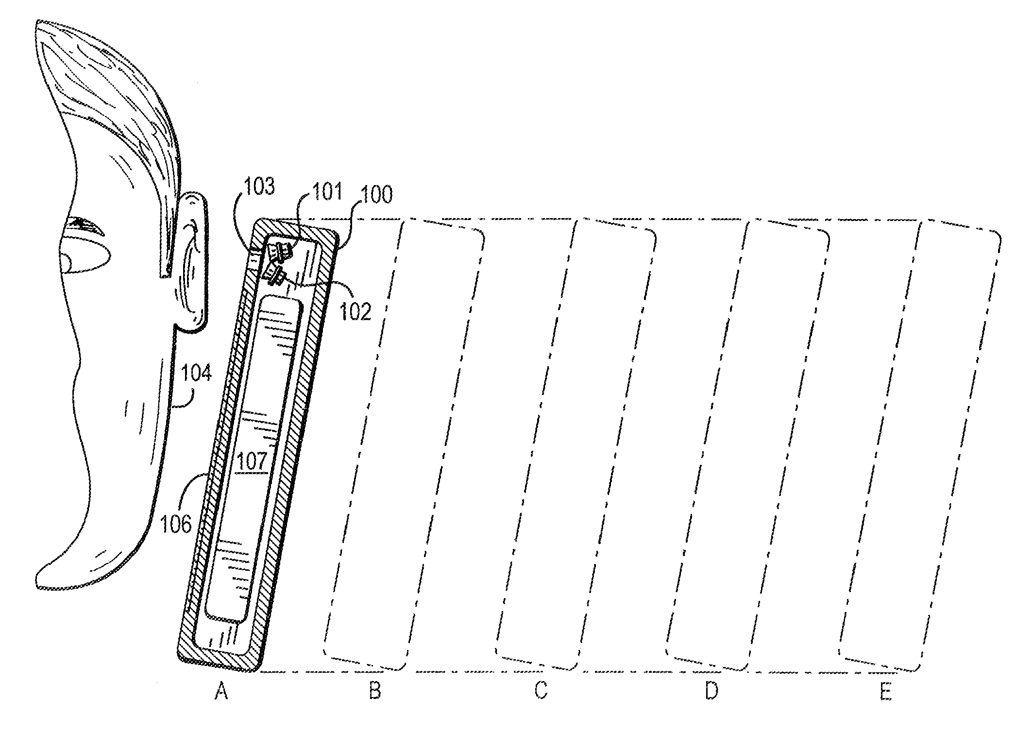
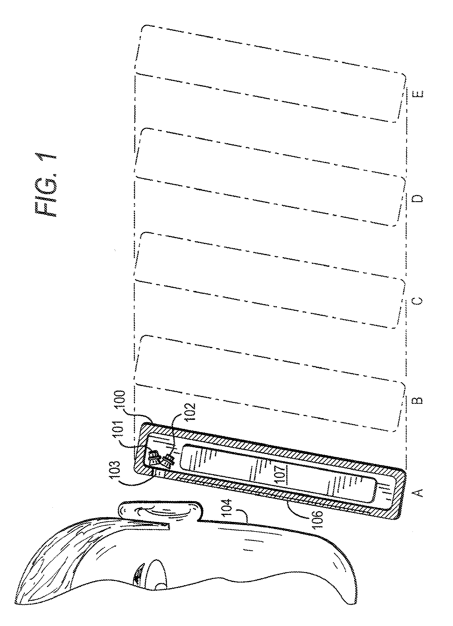
[0031]In circuitry 500 according to the invention, shown in FIG. 5, each transducer 101, 102 is driven by a respective variable gain amplifier 504, each of which receives the output of audio source 301. A demultiplexer / splitter (not shown) may be provided at node 503 between audio source 301 and amplifiers 504. User input 302 and proximity signal 401 are provided to a microprocessor 501 (or a microprocessor-controlled digital signal processor) which processes signals 302, 401 to determine how to control each of amplifiers 504. Microprocessor 501 thus determines which of transducers 101, 102 is active, and at what volume level, based on signals 302, 401. Unlike circuitry 400 of FIG. 4, in which demultiplexer / splitter 303 can select only one of transducers 101, 102, and in which only one of transducers 101, 102 can be active at any one time, circuitry 500 can activate both transducers 101, 102 at appropriate levels because microprocessor 501 can simultaneously output control signals t...
third embodiment
[0032]circuitry 600 according to the invention, shown in FIG. 6, is similar to circuitry 400 of FIG. 4, except that proximity signal 401 is shown only controlling demultiplexer / splitter 303 to activate either transducer 101, 102. The volume of the selected transducer 101, 102 may be controlled separately (not shown), or may be dependent entirely on the level of the output of audio source 301, however that level may be controlled (not shown).
PUM
 Abstract
Description
Claims
Application Information
 - R&D
- Intellectual Property
- Life Sciences
- Materials
- Tech Scout
- Unparalleled Data Quality
- Higher Quality Content
- 60% Fewer Hallucinations
Browse by: Latest US Patents, China's latest patents, Technical Efficacy Thesaurus, Application Domain, Technology Topic, Popular Technical Reports.
© 2025 PatSnap. All rights reserved.Legal|Privacy policy|Modern Slavery Act Transparency Statement|Sitemap|About US| Contact US: help@patsnap.com


