Implantable catheter lead or electrode lead

a technology of electrode lead and catheter lead, which is applied in the field of implantable catheter lead or electrode lead, can solve the problems of general non-explantability, reduce and less stringent demands on the operator's skill, and reduce the trauma to the body cavity or vascular wall

Inactive Publication Date: 2013-05-28
BIOTRONIK SE & CO KG
View PDF14 Cites 34 Cited by
  • Summary
  • Abstract
  • Description
  • Claims
  • Application Information

AI Technical Summary

Benefits of technology

[0006]The invention is based on the idea that the electrode, after a certain period of time in which protection against dislocation by overgrowing tissue cannot yet be provided and the lead's fixation means must provide this protection, is no longer securely attached by fixation means, or the fixation means have disintegrated to such an extent that they have largely lost their fixation effect. It is then comparatively easy to remove the electrode lead from the vessel or bodily cavity without traumatization as a result of “tearing out” the fixation means. One version of the invention thus provides a releasable attachment such that explantation of the catheter lead or electrode lead is possible after release of the attachment while the fixation means remains in place within the body of the patient. In another version of the invention, elements made of resorbable foam or nonwoven material are provided as fixation means that dissolve within the body, after which explantation of the lead is also easily possible.
[0010]In an especially simple version of the invention, the attachment has a resorbable, disintegratable or destroyable retaining ring that secures the fixation means to the lead body only in its intact initial state. This version is especially simple and inexpensive to fabricate since, first of all, suitably formed fixation means can easily be slid onto the lead body. The retaining ring is then in turn mounted on these means, and this ring presses these against the lead body as long as the body maintains its integrity. This nonpositive attachment is supported by a positive attachment between the lead body and fixation means, or can be replaced entirely by a positive attachment between the lead body, fixation means, and retaining ring.
[0016]In another version of the invention, the fixation means are disposed at a distance from the distal end of the lead. As a result, it becomes possible, for example, to anchor an electrode line projecting by its distal end into a vessel both at one entrance or one wall of the vessel, but not within the vessel itself, and thus preclude a disturbance the blood flow by the fixation means or an unwanted proliferation of the vessel by tissue growing around the fixation means.
[0017]In another version of the invention, the fixation means have a spreading element that is expandable by the lead body or that is self-expanding in response to activation of the fixation means. This can involve a single anchor-like element; however, what is preferred is an version in which the fixation means has a group of spreading elements that are distributed in particular around the circumference of the lead body, and that surround this body in particular in a funnel-shape, calyx-shape, or tulip-shape when in the activated state. Such a group of fixation means generally provides a secure foothold for the electrode lead until the time of ingrowth, and also places less stringent demands on the skill of the operator.
[0018]In another advantageous version of the invention, the self-expanding spreading element, or the group of spreading elements, is designed as a metal component elastically pretensioned in the active state, in particular, one composed of Nitinol or a similarly effective metal alloy. In addition, it is useful if each spreading element is designed in a spade shape, plate shape, coil shape, spiral shape, or helical shape, or has correspondingly designed ends, in order to reduce trauma to the body cavity or vascular wall during fixation.

Problems solved by technology

As a result, they are generally no longer explantable.

Method used


Image

  • Implantable catheter lead or electrode lead
  • Implantable catheter lead or electrode lead
  • Implantable catheter lead or electrode lead

Examples


Embodiment Construction

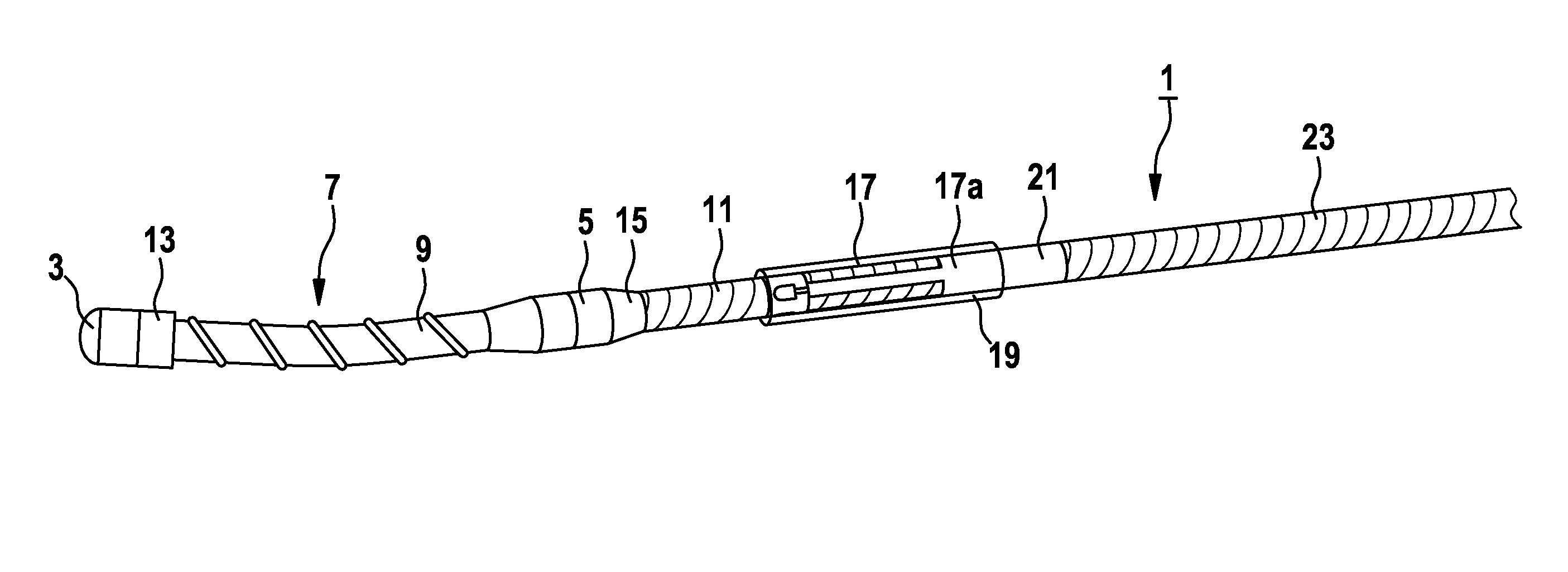
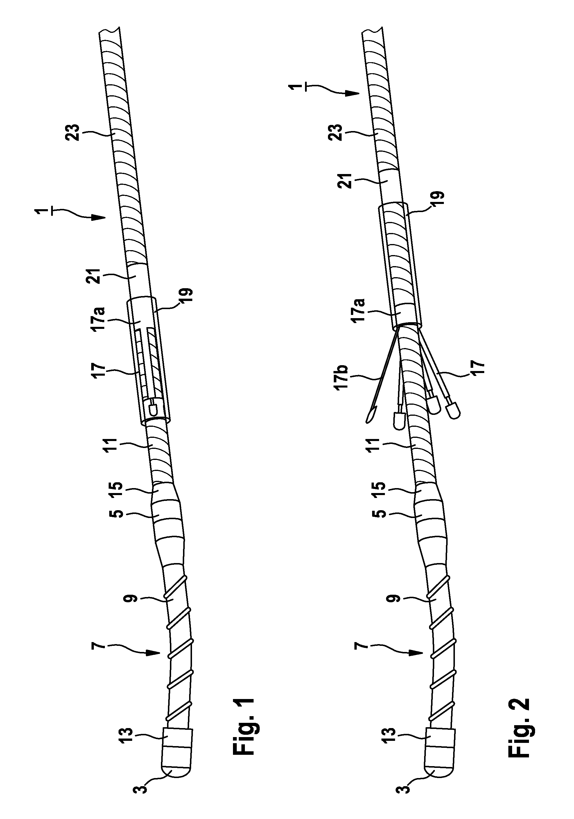
[0027]FIGS. 1 and 2 illustrate the distal section of a pacemaker electrode lead 1 having a tip electrode 3 disposed at the distal end, and a ring electrode 5 spaced a certain distance therefrom on a flexible plastic lead body 7 that can be composed, for example, of silicon tube with a Parylene coating which can enhance the sliding properties. Coiled electrode leads 9 and 11 run within lead body 7, and x-ray markers 13 and 15 are provided at the sites of tip electrode 3 and the ring electrode 5. In a preferred version, electrodes 3 and 5 can themselves be designed as x-ray markers.

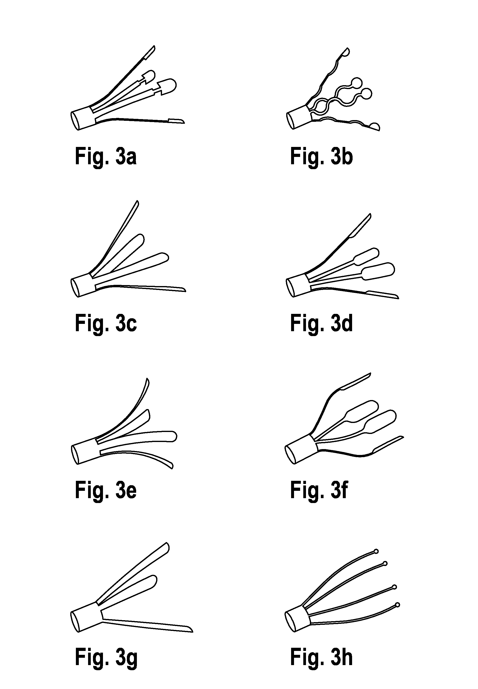
[0028]A spreading element 17 composed of Nitinol is clamped onto lead body 7, which body in the inactive state shown in FIG. 1 is held by a tubular sleeve 19 that has a platinum stop ring 21 and is slipped from the proximal end of electrode lead 1 over this lead. These are mounted on the front (distal) end of a polyurethane (PU) tube 23 that has a slip-type coating. In this state, the pacemaker electrode le...


PUM


Abstract

An implantable catheter lead or electrode lead includes an elongated flexible lead body with the fixation means attached to the lead body, for the purpose of effecting fixation of the catheter lead or electrode lead in a predetermined position within a vessel or a bodily cavity of a patient. A releasable attachment is provided between the lead body and the fixation means such that an explantation of the catheter lead or electrode lead is possible after the attachment is released while the fixation means remains in place within the body of the patient.

Description

FIELD OF THE INVENTION[0001]The invention relates to an implantable catheter lead or electrode lead including an elongated flexible lead body, and including fixation means connected to the lead body to effect fixation of the lead at a predetermined position within a vessel or a body cavity of a patient.BACKGROUND OF THE INVENTION[0002]In this document, a “catheter lead” or “electrode lead” refers to any catheter to be affixed within the body of a human being or an animal, or any type of electrode lead for at least temporary intracorporal fixation. Examples include catheters for supplying fluids or objects into bodily cavities or vessels, or for draining fluids from these, pacemaker electrode leads, shock electrode leads, vascular stimulation leads, etc.[0003]Many such catheter leads or electrode leads have long been known, and an extremely diverse variety of these are commercially available. When developing the technology for pacemakers and cardioveters, special attention was paid t...

Claims


Application Information

Patent Timeline
Patent Type & Authority Patents(United States)
IPC IPC(8): A61N1/00A61B17/08
CPCA61N1/057A61N2001/0578A61N2001/0585
Inventor FLACH, ERHARDLANDGRAF, TASSILODOCE, ENLEN
Owner BIOTRONIK SE & CO KG
Why Eureka
Try Eureka