EGR venturi diesel injection

a diesel injection and exhaust gas technology, applied in the direction of exhaust gas recirculation, liquid fuel feeders, non-fuel substance addition to fuel, etc., can solve the problems of increased fuel consumption and smoke development, inefficient recirculation of exhaust gas, and reduced engine power

Inactive Publication Date: 2013-06-04
CONCENTRIC SKANES FAGERHULT
View PDF23 Cites 4 Cited by
  • Summary
  • Abstract
  • Description
  • Claims
  • Application Information

AI Technical Summary

Problems solved by technology

During the turbo charging of diesel, for example, although not limited thereto, the pressure of the exhaust gases in most cases is less than the intake air, and exhaust gases can therefore not be efficiently recirculated without measures being taken for achieving a sufficient supply of exhaust gases.
However, traditional venturi solutions have been associated with disadvantages in the form of, for example, reduced engine power through high pressure losses, together with increased fuel consumption and smoke development.
However, injecting the fuel directly in the cylinders does not allow for optimum fuel / air mixture for combustion.

Method used


Image

  • EGR venturi diesel injection
  • EGR venturi diesel injection
  • EGR venturi diesel injection

Examples


Embodiment Construction

[0018]The present teachings are described more fully hereinafter with reference to the accompanying drawings, in which the present embodiments are shown. The following description is presented for illustrative purposes only and the present teachings should not be limited to these embodiments.

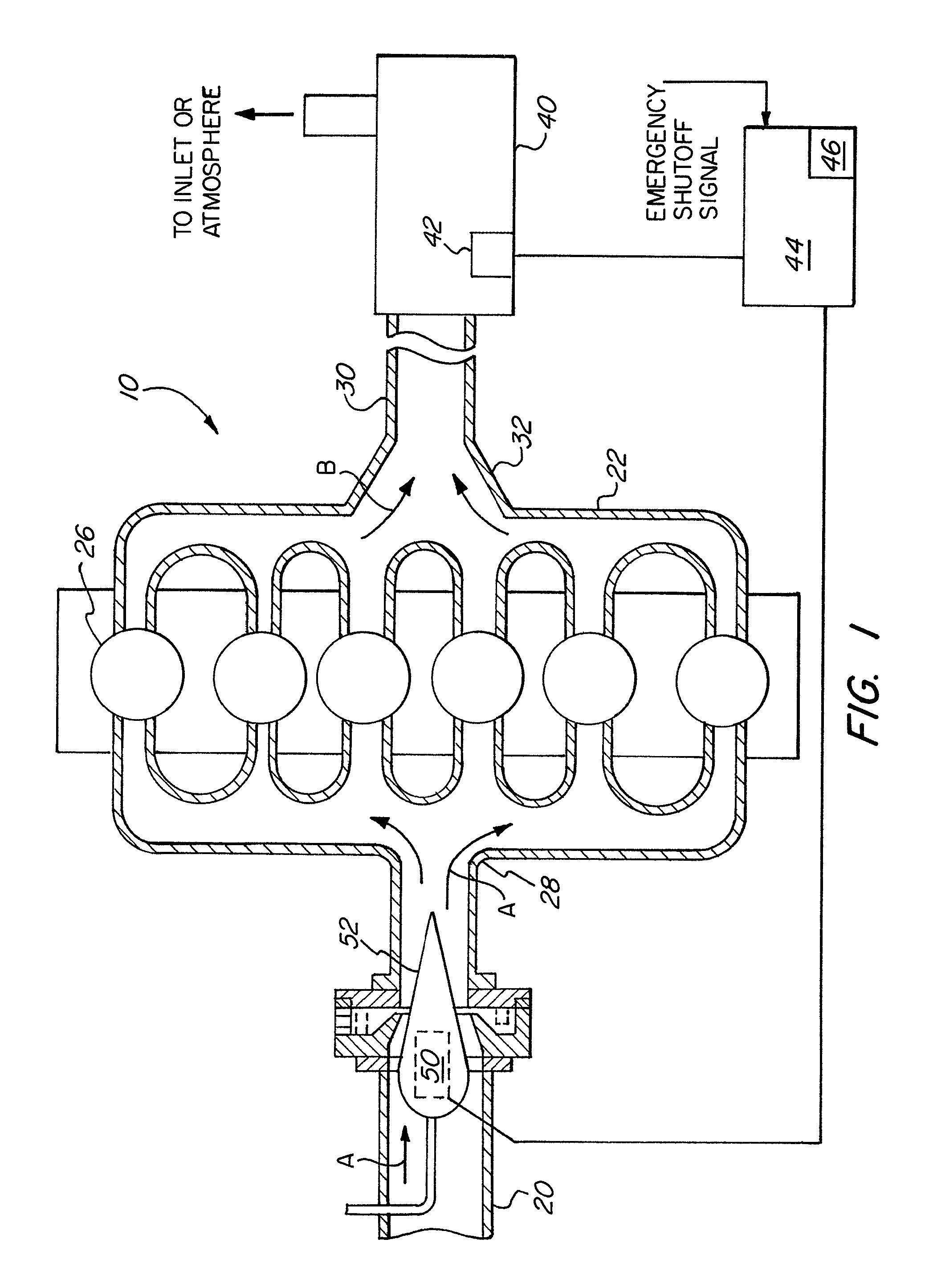
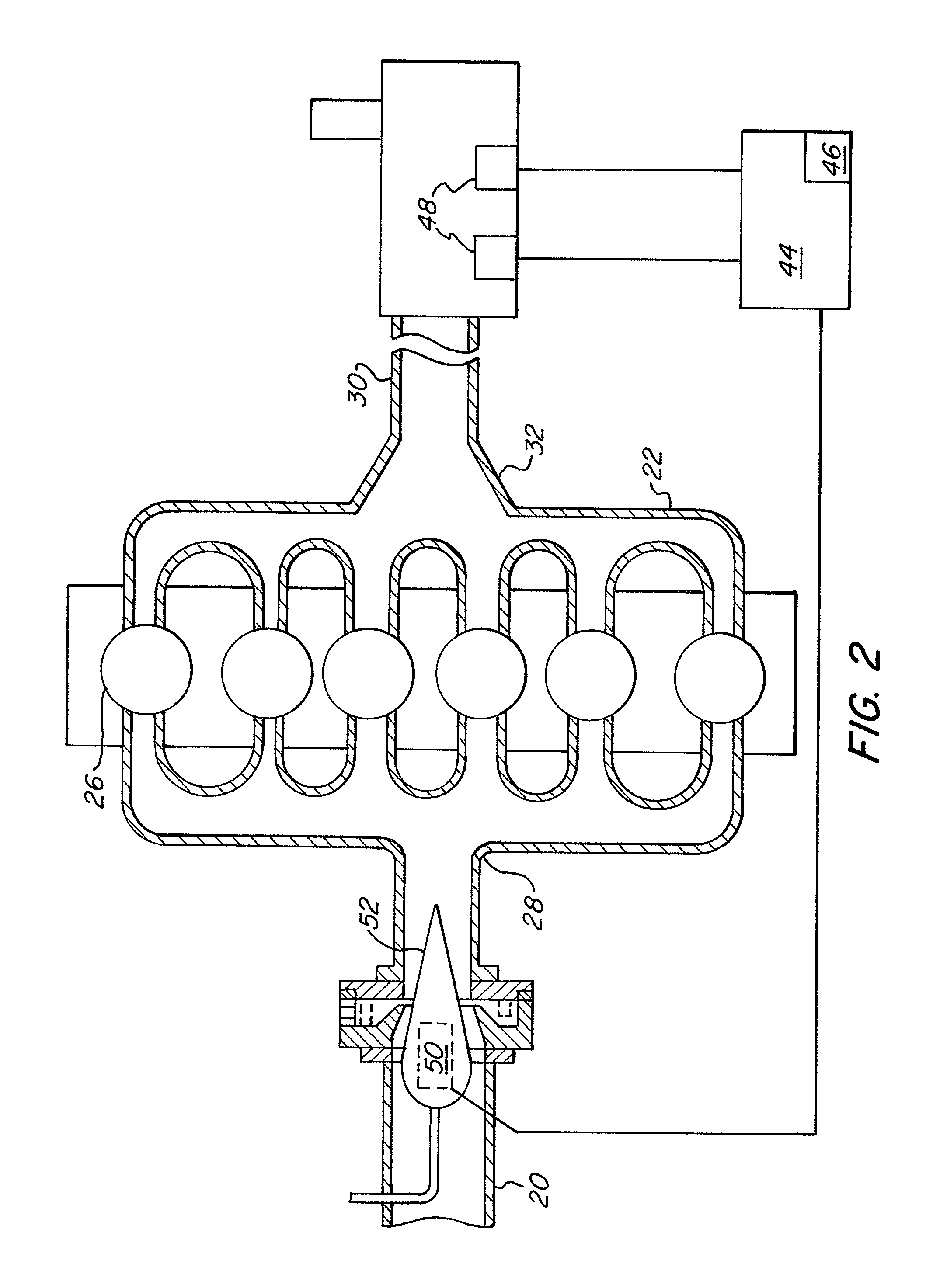
[0019]The basic components of one embodiment of an engine intake control system 10 in accordance with the teachings are illustrated in FIG. 1. As used in the description, the terms “top,”“bottom,”“above,”“below,”“over,”“under,”“above,”“beneath,”“on top,”“underneath,”“up,”“down,”“upper,”“lower,”“front,”“rear,”“back,”“forward” and “backward” refer to the objects referenced when in the orientation illustrated in the drawings, which is not necessary for achieving the objects of the present teachings.

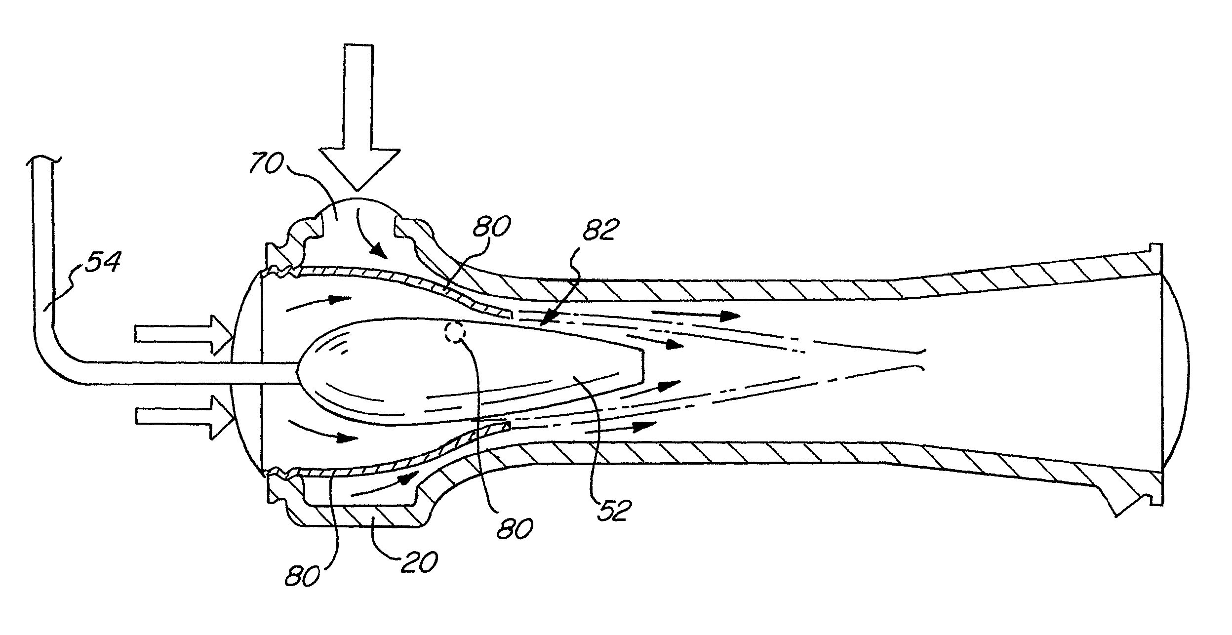
[0020]The present teachings involve the injection of fuel into EGR (exhaust gas recirculation) for internal combustion engines, including diesel and gasoline engines, although not limited thereto. Genera...


PUM


Abstract

An arrangement for mixing a first and a second gas flow, for example, an inlet flow with an exhaust gas return flow in a diesel engine. An air conduit has an inlet for the first flow and an inlet for the second flow, in order to achieve the mixing. A valve body is arranged to be displaced in the longitudinal direction of the air conduit at the inlet for the second flow in order to achieve a variable venturi effect and in this way a variable suction effect and mixture of the mixed flow. One or more fuel injectors inject fuel into the air conduit to pre-mix fuel with the first and second gas flows before reaching the engine cylinders for combustion.

Description

FIELD OF THE INVENTION[0001]The present teachings relate generally to exhaust gas recirculation in internal combustion engines and, more particularly, to a diesel fuel-injected exhaust gas recirculation system.BACKGROUND OF THE INVENTION[0002]As is well known, internal combustion engines operate by introducing fuel into fuel cylinders. Energy is released in the form of expanding gas due to rapid combustion of the fuel, which acts upon pistons and converts the chemical energy of the fuel into mechanical energy. The pistons are connected to a crankshaft, and the linear, up-and-down motion of the pistons translates into the rotary motion needed to turn the wheels of a vehicle. In order to produce the rapid combustion, fuel is mixed with intake air, either before or after the air is compressed, and then ignited in order to cause combustion. After this combustion takes place, the leftover exhaust gases are forced out of the cylinder and subsequently expelled into the environment or, more...

Claims


Application Information

Patent Timeline
Patent Type & Authority Patents(United States)
IPC IPC(8): F02B47/08F02M25/07
CPCF02M35/10177F02M35/10222F02M69/043F02M35/10118F02D9/12F02M25/0722Y02T10/121F02M26/19F02B47/08
Inventor HOLM, LARS THOMAS
Owner CONCENTRIC SKANES FAGERHULT
Why Eureka
Try Eureka