Centrifugal compressor assembly and method

a centrifugal compressor and compressor technology, applied in the field of compressors, can solve the problems of high reliability of centrifugal chillers, low maintenance requirements, and large energy consumption of centrifugal chillers in commercial and other high cooling and/or heating demand facilities

Active Publication Date: 2009-08-20
TRANE INT INC
View PDF92 Cites 30 Cited by
  • Summary
  • Abstract
  • Description
  • Claims
  • Application Information

AI Technical Summary

Benefits of technology

[0009]In yet another preferred embodiment, a chiller system is provided comprising an evaporator; a condenser; and a multistage centrifugal compressor for compressing refrigerant. The evaporator, the condenser; and the multistage centrifugal compressor are connected in a closed loop. The multistage centrifugal compressor further comprising: a shaft; a motor mounted in a motor housing; said motor for driving the shaft at a range of sustained operating speeds; a variable speed drive for varying operation of the motor within the range of sustained operating speeds; a final stage compressor and a non-final stage compressor mounted on the shaft. Each compressor comprises: a compressor housing; said compressor housing having a compressor inlet for receiving the refrigerant and a compressor outlet for deliveri...

Problems solved by technology

Typically, the reliability of centrifugal chillers is high, and the maintenance requirements are low.
Centrifuga...

Method used


Image

  • Centrifugal compressor assembly and method
  • Centrifugal compressor assembly and method
  • Centrifugal compressor assembly and method

Examples


Embodiment Construction

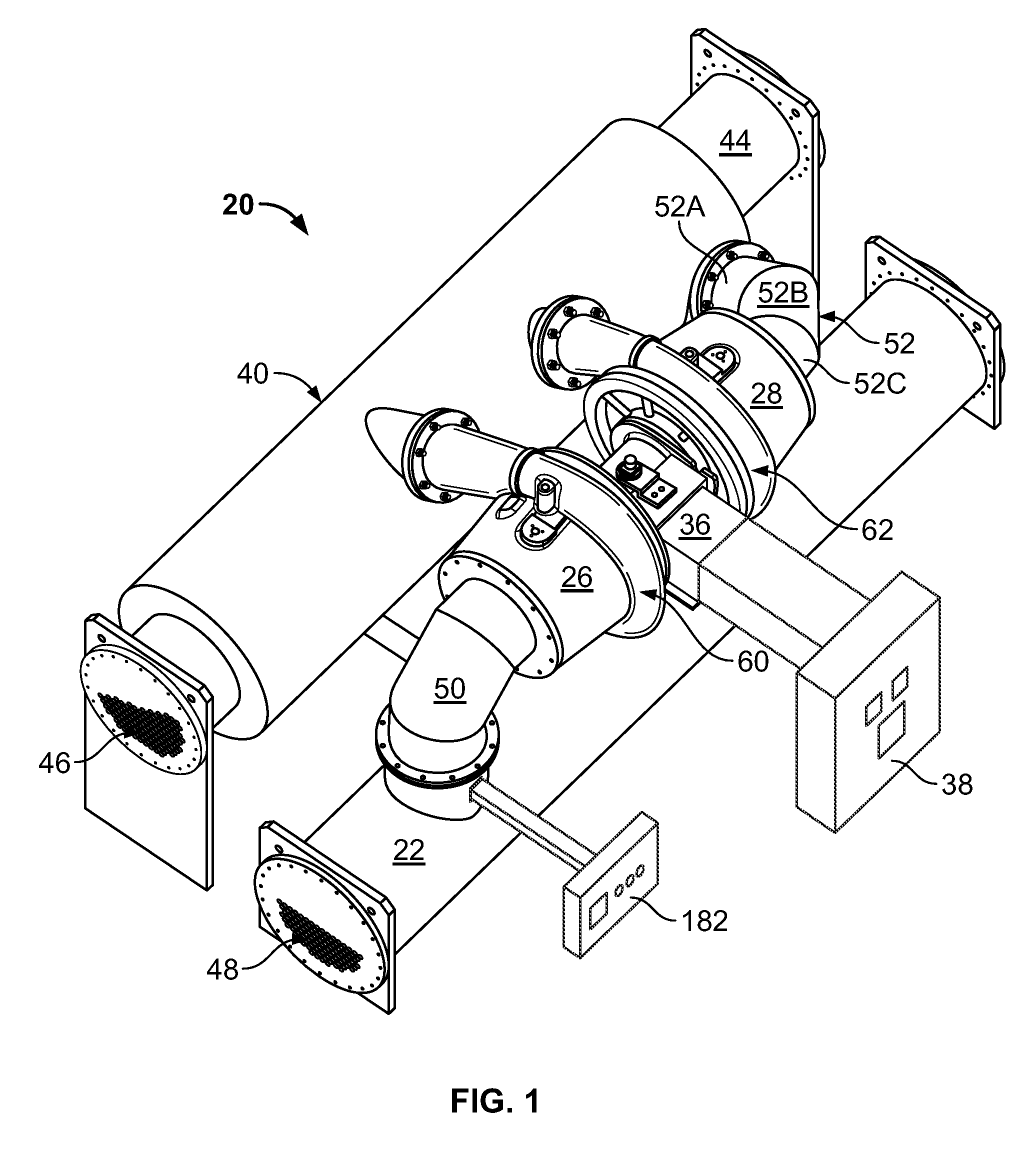
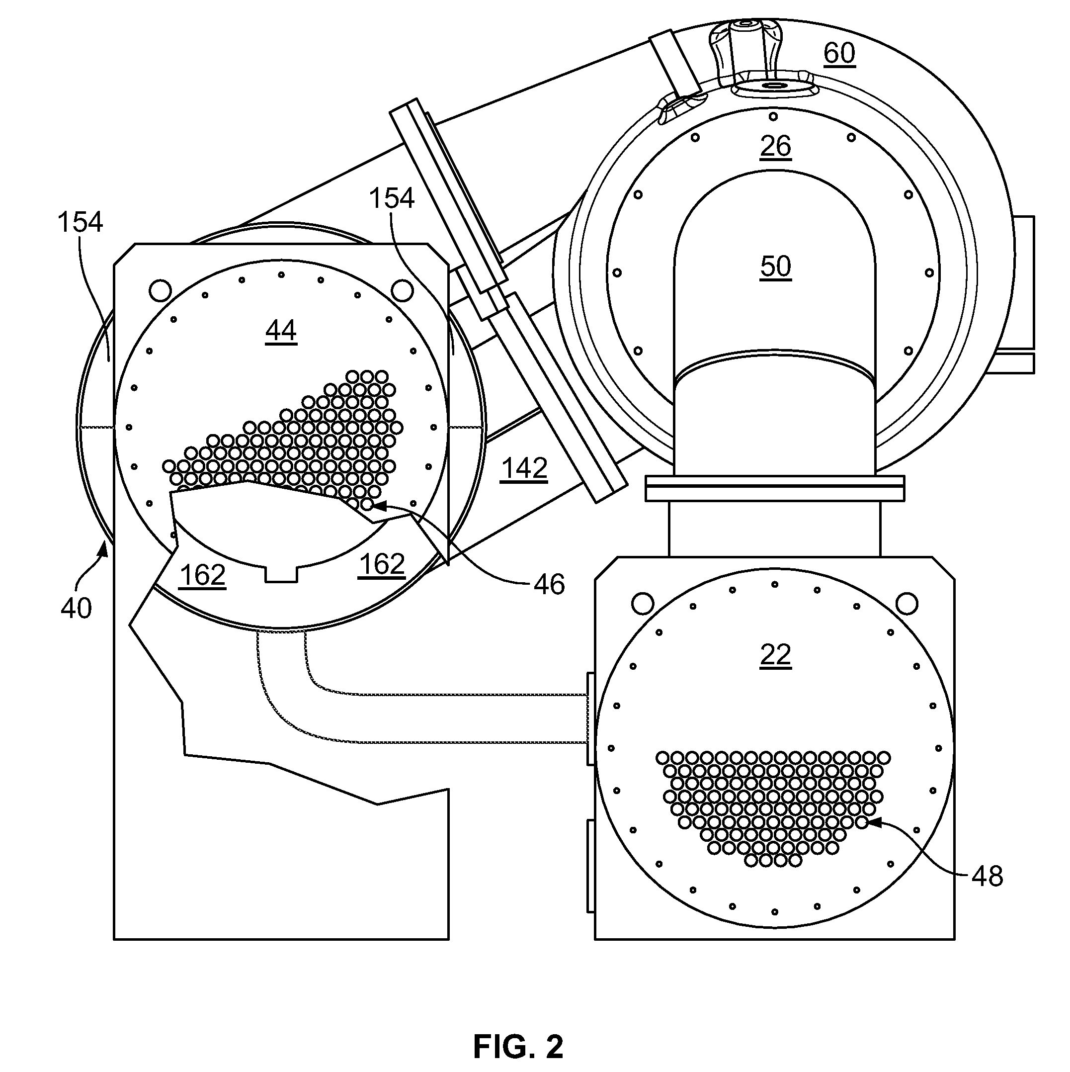
[0031]Referring to FIGS. 1-3 of the drawings, a chiller or chiller system 20 for a refrigeration system. A single centrifugal chiller system, and the basic components of chiller 20 are illustrated in FIGS. 1-3. The chiller 20 includes many other conventional features not depicted for simplicity of the drawings. In addition, as a preface to the detailed description, it should be noted that, as used in this specification and the appended claims, the singular forms “a,”“an,” and “the” include plural referents, unless the context clearly dictates otherwise.

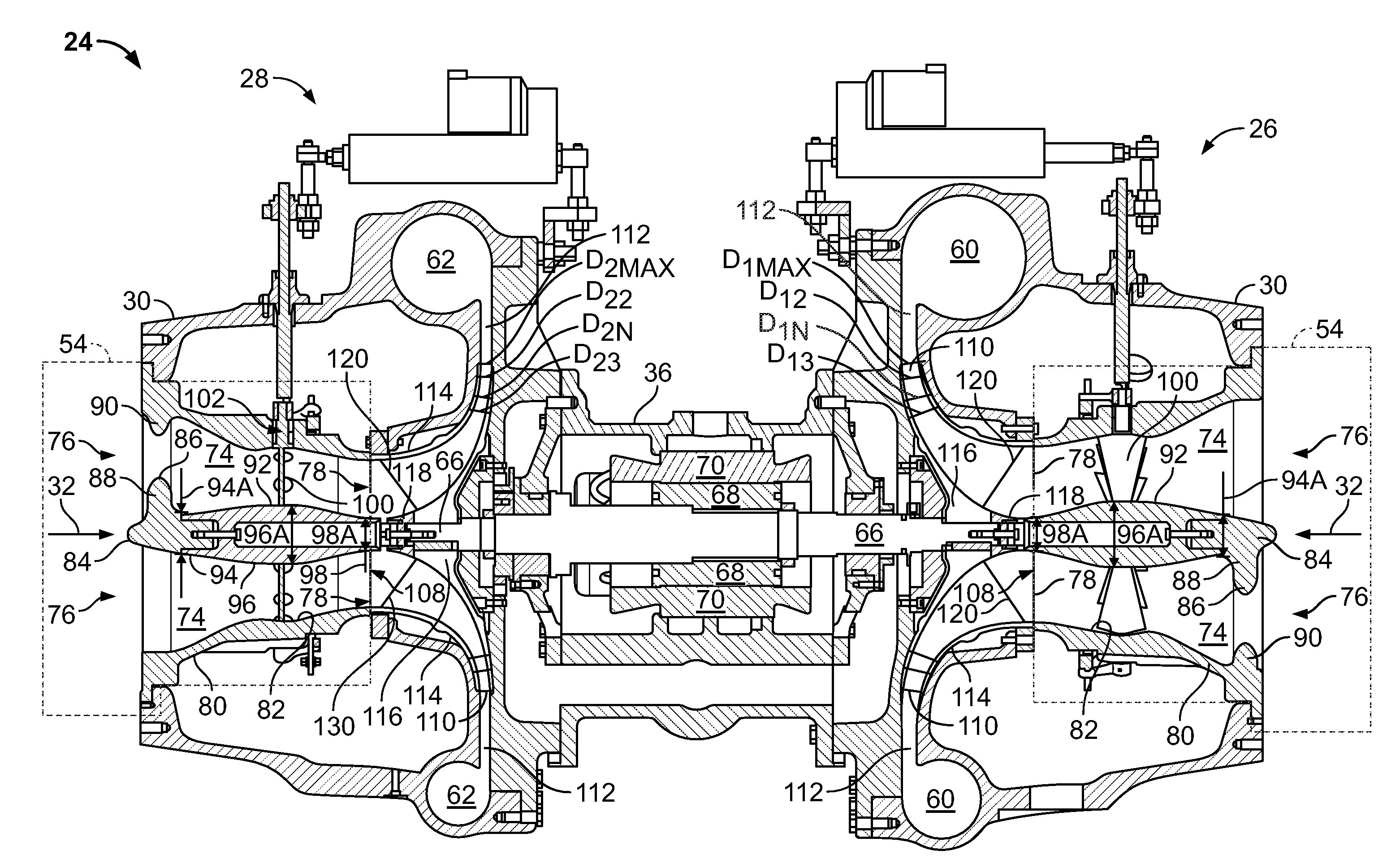
[0032]In the embodiment depicted, chiller 20 is comprised of an evaporator 22, multi-stage compressor 24 having a non-final stage compressor 26 and a final stage compressor 28 driven by a variable speed, direct drive permanent magnet motor 36, and a coaxial economizer 40 with a condenser 44. The chiller 20 is directed to relatively large tonnage centrifugal chillers in the range of about 250 to 2000 tons or larger.

[0033]In a preferred...


PUM

PropertyMeasurementUnit
Angleaaaaaaaaaa
Angleaaaaaaaaaa
Angleaaaaaaaaaa

Abstract

A centrifugal compressor assembly for compressing refrigerant in a 250-ton capacity or larger chiller system comprising a motor, preferably a compact, high energy density motor or permanent magnet motor, for driving a shaft at a range of sustained operating speeds under the control of a variable speed drive. Another embodiment of the centrifugal compressor assembly comprises a mixed flow impeller and a vaneless diffuser sized such that a final stage compressor operates with an optimal specific speed range for targeted combinations of head and capacity, while a non-final stage compressor operates above the optimum specific speed of the final stage compressor. Another embodiment of the centrifugal compressor assembly comprises an integrated inlet flow conditioning assembly comprising a flow conditioning nose, a plurality of inlet guide vanes and a flow conditioning body that positions inlet guide vanes to condition flow of refrigerant into an impeller to achieve a target approximately constant angle swirl distribution with minimal guide vane turning.

Description

BACKGROUND OF THE INVENTION[0001]The present invention generally pertains to compressors used to compress fluid. More particularly, embodiments of the present invention relate to a high-efficiency centrifugal compressor assembly, and components thereof, for use in a refrigeration system. An embodiment of the compressor assembly incorporates an integrated fluid flow conditioning assembly, fluid compressor elements, and a permanent magnet motor controlled by a variable speed drive.[0002]Refrigeration systems typically incorporate a refrigeration loop to provide chilled water for cooling a designated building space. A typical refrigeration loop includes a compressor to compress refrigerant gas, a condenser to condense the compressed refrigerant to a liquid, and an evaporator that utilizes the liquid refrigerant to cool water. The chilled water is then piped to the space to be cooled.[0003]One such refrigeration or air conditioning system uses at least one centrifugal compressor and is ...

Claims


Application Information

Patent Timeline
IPC IPC(8): F25B1/10F01D5/22F01D5/14B23P15/04
CPCF04D17/122F04D27/0246Y10T29/49329F04D29/441F25B1/053F04D29/286F04D29/284F04D29/444
Inventor HALEY, PAUL F.
Owner TRANE INT INC
Why Eureka
Try Eureka