In-wheel motor system for a steering wheel

a technology of in-wheel motor and steering wheel, which is applied in the direction of non-deflectable wheel steering, electric propulsion mounting, transportation and packaging, etc., can solve the problems of large steering torque, large variations in the ground contact force of tires, and easy resonance in steering directions, so as to improve the ground contact performance of tires and riding comfort, the effect of reducing the steering torque of the steering wheel

Inactive Publication Date: 2013-06-04
BRIDGESTONE CORP
View PDF17 Cites 18 Cited by
  • Summary
  • Abstract
  • Description
  • Claims
  • Application Information

AI Technical Summary

Benefits of technology

[0008]According to a first aspect of the present invention, there is provided an in-wheel motor system for mounting a direct drive motor to a steering wheel, comprising a first knuckle which is connected to the non-rotary side of the direct drive motor and locked in a steering direction and a second knuckle which is connected to a steering rod and to the first knuckle in such a manner that it can turn on a king pin axis in the steering direction and fitted with a brake unit and the steering wheel. Thereby, as the in-wheel motor does not turn in the steering direction at the time of steering, the steering torque of the steering wheel can be reduced without fail.
[0009]According to a second aspect of the present invention, there is provided an in-wheel motor system for a steering wheel, wherein the non-rotary side of the motor is connected to the first knuckle by elastic bodies and dampers, or elastic bodies having a spring or damper function. Thereby, the motor is float mounted to a frame dress-up part to function as the weight of a dynamic damper, thereby making it possible to improve the ground contact performance of the tire and riding comfort.
[0010]According to a third aspect of the present invention, there is provided an in-wheel motor system for a steering wheel, wherein the non-rotary side of the motor is supported by direct-moving guides and a buffer member in the vertical direction of a vehicle. Thereby, variations in the ground contact pressure of the tire at the time of driving on a rough road and the road holding properties of the vehicle can be improved.
[0011]According to a fourth aspect of the present invention, there is provided an in-wheel motor system for a steering wheel, wherein the non-rotary side of the motor is supported by direct-moving guides and a buffer member in the horizontal direction of a vehicle in addition to the vertical direction. Thereby, variations in the longitudinal force of the tire can be reduced and the tire performance can be stabilized.
[0012]According to a fifth aspect of the present invention, there is provided an in-wheel motor system for a steering wheel, wherein the output shaft of the motor and a wheel support hub mounted to the second knuckle are interconnected by constant velocity joints. Thereby, even when the motor shaft becomes eccentric from the wheel shaft by steering drive force can be transmitted from the motor to the wheel without fail.
[0013]According to a sixth aspect of the present invention, there is provided an in-wheel motor system for a steering wheel, wherein the rotary portion of the motor and the wheel are interconnected by a flexible coupling having at least two direct-moving guides connected to each other in such a manner that their moving directions cross each other in the axial direction of the motor and a constant velocity joint-like coupling which has the center of its movement on a king pin axis. Thereby, even when a hollow type direct drive motor which cannot directly transmit the revolution of the motor to the hub due to its structure is used as the in-wheel motor, drive force can be transmitted from the motor to the wheel without fail.

Problems solved by technology

That is, as the inertia moment on the steering axis of the steering wheel provided with the in-wheel motor increases due to the mass of the motor, not only does the steering torque becomes large but also the resonance in the steering direction easily occurs.
In a vehicle having a suspension mechanism such as a spring, it is known that as the mass of unsprung parts such as a wheel, knuckle and suspension arm so called “unsprung mass” increases, variations in the ground contact force of a tire become larger and the road holding properties become worse when the vehicle runs on a rough road.
In the in-wheel motor of the prior art, as the motor is fixed to the knuckle as described above, the above unsprung mass increases by the mass of the motor with the result that variations in the ground contact force of the tire become larger and the road holding properties become worse.

Method used


Image

  • In-wheel motor system for a steering wheel
  • In-wheel motor system for a steering wheel
  • In-wheel motor system for a steering wheel

Examples


embodiment 1

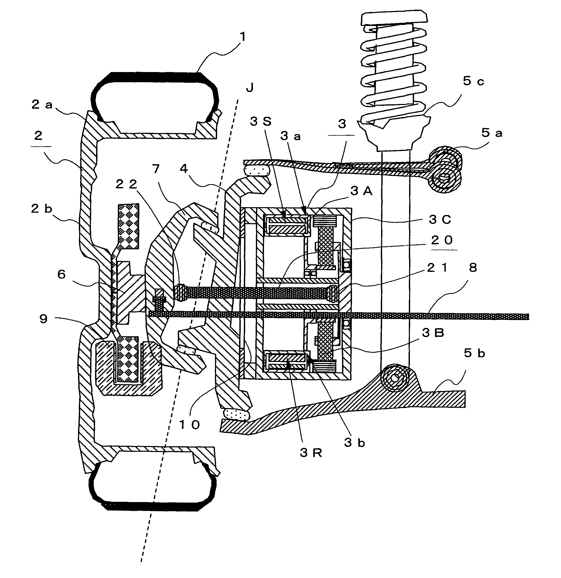
[0024]FIG. 1 is a diagram showing the constitution of an in-wheel motor system for a steering wheel according to Embodiment 1. In FIG. 1, reference numeral 1 denotes a tire, 2 a wheel composed of a rim 2a and a wheel disk 2b, 3a geared motor comprising an electric motor 3A and a planetary speed reducer 3B in a motor case 3C, 4 a first knuckle which is fitted with the above geared motor 3 and connected to upper and lower suspension arms 5a and 5b, 6a wheel support hub which is connected to the wheel 2 at its rotation axis, 7 a second knuckle which is connected to a steering rod 8 and to the first knuckle 4 in such a manner that it can turn on a king pin axis J in the steering direction. A brake unit 9 and the above wheel 2 are mounted to the second knuckle 7 through the above wheel support hub 6.

[0025]That is, the in-wheel motor system for a steering wheel of the present invention is constituted such that the knuckle consists of the first knuckle 4 locked in the steering direction an...

embodiment 2

[0033]In the above Embodiment 1, the in-wheel motor is the geared motor 3. Even when a hollow type direct drive motor 3Z constituted such that a stator 3S is mounted on a first annular case (non-rotary case) 3a which is open on the outer side in the radial direction, a rotor 3R is mounted on a second annular case (rotary case) 3b which is open on the inner side in the radial direction and arranged concentric to the above non-rotary case 3a on the outer side in the radial direction of the non-rotary case 3a with a predetermined space between it and the above stator 3S, and the above non-rotary case 3a and the rotary case 3b are rotatably interconnected by a bearing 3j is mounted as shown in FIG. 3 and FIG. 4, the knuckle consists of a first knuckle 4Z which is connected to the non-rotary side of the above motor 3Z by a shock absorber 30 and locked in the steering direction by upper and lower suspension arms 5a and 5b and a second knuckle 7Z which is connected to the steering rod 8 an...


PUM


Abstract

An in-wheel motor system for mounting a direct drive motor to a steering wheel comprises a first knuckle 4 which is connected to the non-rotary side of a geared motor 3 by a connection member I0 having elastic bodies and direct-moving guides for limiting movement to a vertical direction and locked in a steering direction by upper and lower suspension arms 5a and 5b and a second knuckle 7 which is connected to a steering rod 8 and fitted with a brake unit 9 and a wheel 2 through a hub 6. This second knuckle 7 is connected to the above first knuckle 4 in such a manner that it can turn on a king pin axis J in the steering direction and to the output shaft of the above geared motor 3 by a connection shaft 20 having constant velocity joints 21 and 22 at both ends, thereby reducing an increase in steering torque.

Description

BACKGROUND OF THE INVENTION[0001]1. Field of the Invention[0002]The present invention relates to an in-wheel motor system for a steering wheel for use in a vehicle having direct drive wheels as steering wheels.[0003]2. Description of the Prior Art[0004]In recent years, in a vehicle driven by a motor such as an electric car, an in-wheel motor system which incorporates a motor composed of a knuckle as a frame dress-up part and a drive motor in wheels has been employed due to its high space efficiency and drive force transmission efficiency (for example, U.S. Pat. No. 2,676,025, JP-A 9-506236 and JP-A 10-305735) (the term “JP-A” as used herein means an “unexamined published Japanese patent application”).[0005]However, since the motor is fixed to a knuckle which is a frame dress-up part of the vehicle in the above in-wheel motor system of the prior art, when an in-wheel motor is used in the steering wheel, the motor turns in a steering direction together with the wheel at the time of st...

Claims


Application Information

Patent Timeline
Patent Type & Authority Patents(United States)
IPC IPC(8): B60K7/00B60G3/20B60B35/14B60G7/00B60K17/04B60K17/30B60K17/356B62D7/18
CPCB60G3/01B60G7/008B60K7/0007B60K17/30B62D7/18B60G2200/144B60G2200/422B60G2200/44B60G2204/148B60G2204/30B60G2206/50B60G2300/50B60K17/046B60K2007/0038B60K2007/0053B60K2007/0092
Inventor NAGAYA, GO
Owner BRIDGESTONE CORP
Why Eureka
Try Eureka