

Handle device
a technology of a handle and a handle body, which is applied in the direction of anti-theft devices, program control, instruments, etc., can solve the problems of inability to reliably activate the sensor system positioned underneath the metal layer, interference to the functioning, etc., and achieves the effects of simple construction, low cost and avoidance of the disadvantages cited
- Summary
- Abstract
- Description
- Claims
- Application Information
AI Technical Summary
Benefits of technology
Problems solved by technology
Method used
Image

Examples
Embodiment Construction
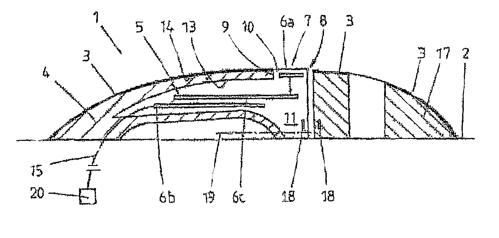
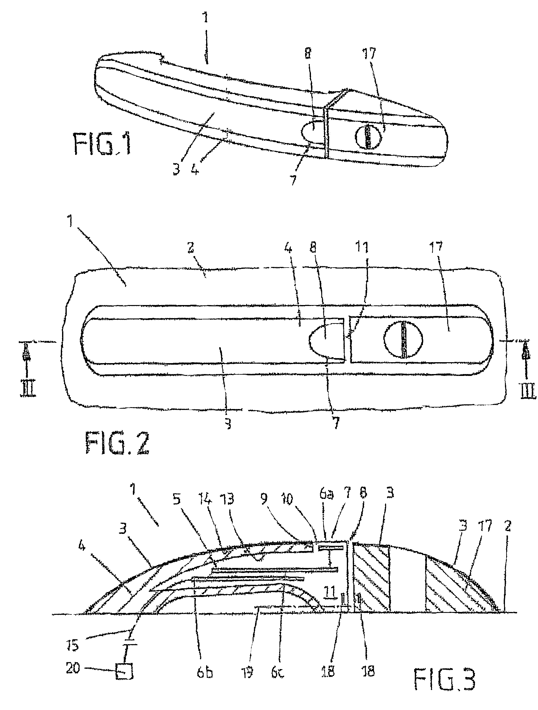
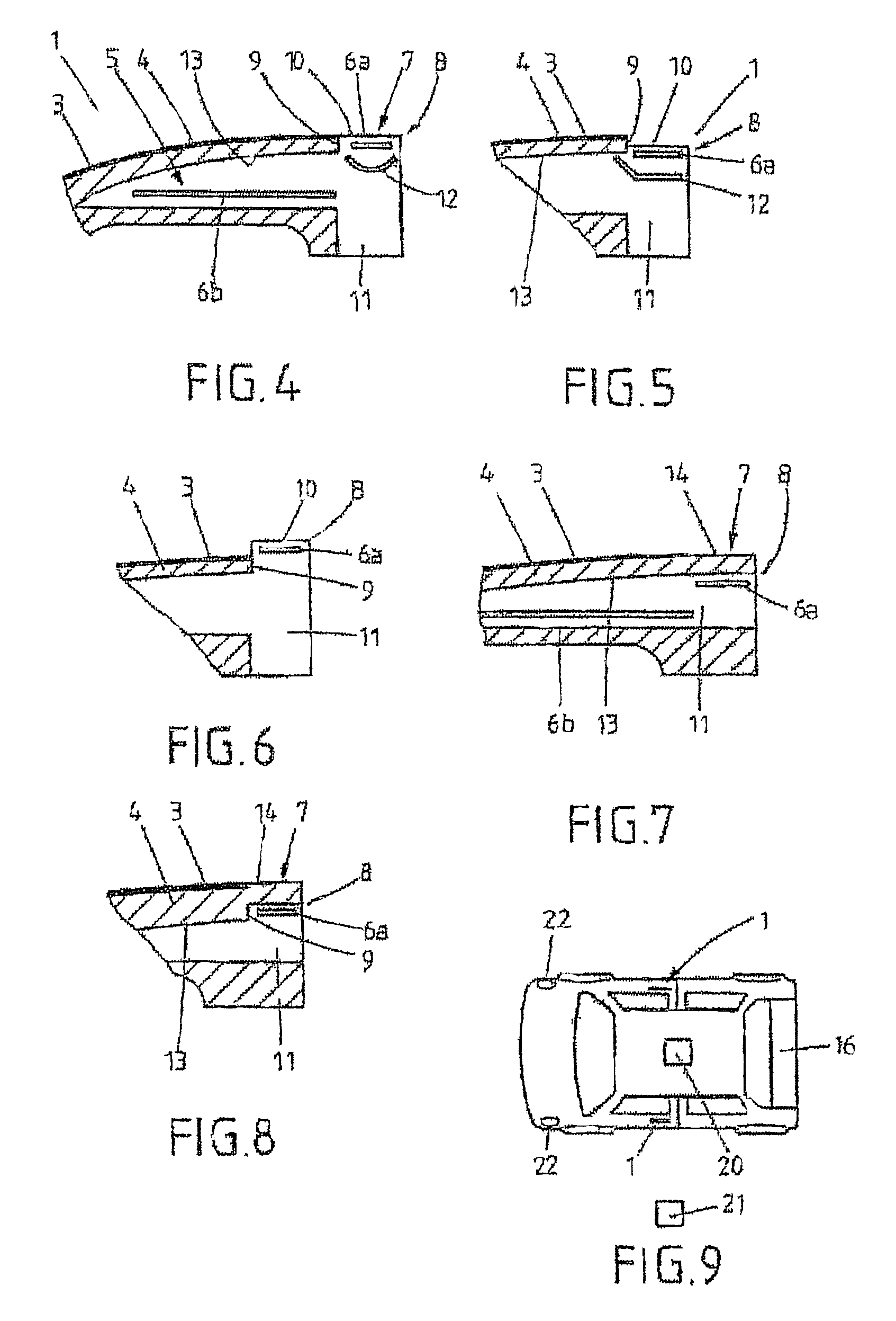
[0035]FIG. 1 shows a handle device 1, having a free surface 7 on its outer shell 4. The free surface 7 is constructed in the form of a recess, embodied on the outer shell 4. As FIG. 2 and in particular FIG. 3 clarify, the free surface 7 is embodied on the side of the handle device 1 facing away from the vehicle door 2. The outer shell 4 in the present exemplary embodiment is an injection-moulded part made of plastic, which has a cavity 5 in its interior. The thin-walled outer shell 4 has on the side facing away from the vehicle door 2 a metal layer 3, which in the exemplary embodiment illustrated is a chrome layer. The said chrome layer can have a thickness of 30 μm to 1 mm, preferably 100 μm to 800 μm and particularly preferably of 300 μm to 600 μm. The handle device 1 further comprises a sensor system 6a, 6b, 6c for the keyless activation of a locking and unlocking system, which is schematically illustrated in FIG. 9.
[0036]As FIG. 3 makes particularly clear, the sensor system 6a, ...
PUM
 Abstract
Description
Claims
Application Information