Projector suspension device including a suspension position adjustment mechanism

a technology of suspension device and position adjustment mechanism, which is applied in the direction of instruments, machine supports, other domestic objects, etc., can solve the problems of large tilt (misalignment) of the projection position, and achieve the effect of convenient design and processing

Active Publication Date: 2013-06-04
SEIKO EPSON CORP
View PDF10 Cites 18 Cited by
  • Summary
  • Abstract
  • Description
  • Claims
  • Application Information

AI Technical Summary

Benefits of technology

[0014]According to this kind of projector suspension device, it is possible to configure a suspension position adjustment mechanism with a simple configuration including the pressing member, screw member, and turning member. Also, with the suspension position adjustment mechanism, it is possible to prevent a rattling due to space between component members by applying a pressing force with the pressing member and, while reliably maintaining an adjusted angle, adjust (fine adjust) the angle formed by the first member and second member by an operation of turning the turning member. Because of this, it is possible to reliably carry out a high precision position adjustment (a fine adjustment) with respect to the projector including the projection optical device having the reflecting mirror. In particular, when the projector is a so-called short focus projector which, including a projection optical device having a reflecting mirror, causes an image magnification projection onto a screen at a short distance, a small tilt (misalignment) of the projector leads to a large tilt (misalignment) of a projection position. As opposed to this, it is highly advantageous that the high precision position adjustment (fine adjustment) which adjusts the small tilt can be reliably carried out using the suspension position adjustment mechanism. Also, by fixing the projector to one of the first member and second member, as well as it being possible to carry out the angle adjustment of the projector, there is no need for an adjustor (a user, or the like) to adjust the projector while holding it, as heretofore known, meaning that it is possible to improve an adjustment operability, and it is possible to reduce a burden of the position adjustment on the adjustor.Application Example 2
[0018]According to this kind of projector suspension device, as the pressing member is formed of a coil spring, it is possible to achieve a further miniaturization of the suspension position adjustment mechanism (a further miniaturization of the projector suspension device), and it becomes easier to design and process the pressing member.

Problems solved by technology

In particular, when the projector is a so-called short focus projector which, including a projection optical device having a reflecting mirror, causes an image magnification projection onto a screen at a short distance, a small tilt (misalignment) of the projector leads to a large tilt (misalignment) of a projection position.

Method used


Image

  • Projector suspension device including a suspension position adjustment mechanism
  • Projector suspension device including a suspension position adjustment mechanism
  • Projector suspension device including a suspension position adjustment mechanism

Examples


embodiment

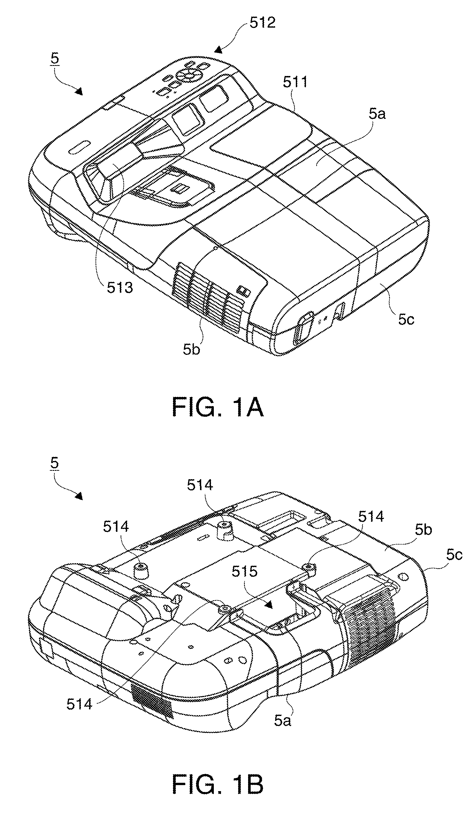
[0031]FIGS. 1A and 1B are perspective views of a projector mounted on a projector suspension device of the embodiment, where FIG. 1A is a perspective view of a condition in which the top surface faces upward, and FIG. 1B is a perspective view of a condition in which the bottom surface faces upward. Referring to FIGS. 1A and 1B, a description will be given of an external configuration, and an operation, of a projector 5.

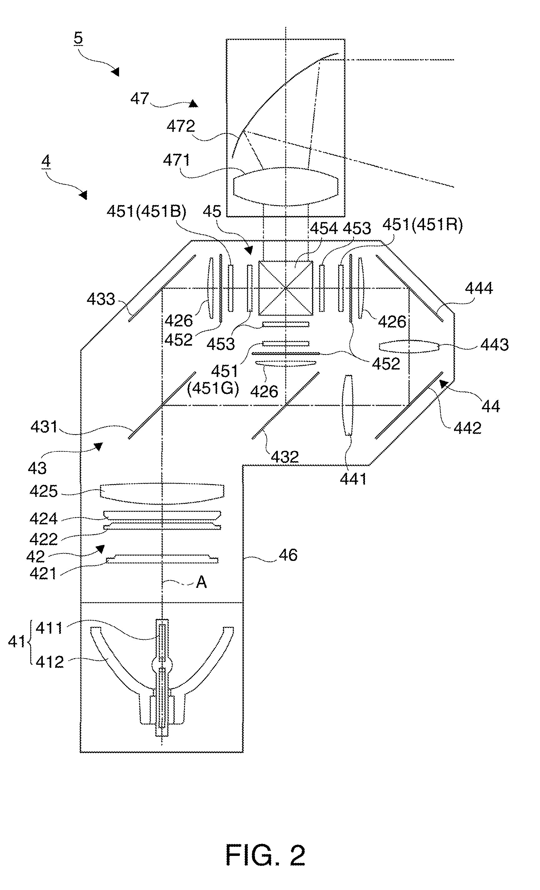
[0032]The projector 5, based on an image signal, modulates a luminous flux emitted from a light source (a light source lamp 41) (refer to FIG. 2) with light modulation elements (liquid crystal panels 451) (refer to FIG. 2), forming an optical image, and projects the optical image onto a screen S (refer to FIGS. 4A and 4B), or the like, as an image (for example, a color image) via a projection optical device 47 (refer to FIG. 2).

[0033]As shown in FIG. 1A, the projector 5 is covered with an exterior housing 511 of an approximately rectangular parallelepiped shape. The p...


PUM


Abstract

A projector suspension device including a projection optical device having a reflecting mirror, and a suspension position adjustment mechanism, the suspension position adjustment mechanism includes: a pressing member which presses a first member and a second member; a screw member which, being fixed in the first member, passes through the second member; and a turning member which, by turning and engaging with the screw member passing through the second member, against the pressing force of the pressing member, adjusts the angle formed by the first member and second member, with a turning pivot set perpendicular to the axial direction of the screw member as the center.

Description

BACKGROUND[0001]1. Technical Field[0002]The present invention relates to a projector suspension device.[0003]2. Related Art[0004]Heretofore, a projector ceiling suspension device has been one to which a projector is fixed suspended from a ceiling. The projector ceiling suspension device, by being installed on the ceiling to fix the projector, causes an image projected from the projector to be projected onto a screen installed on a wall surface of a room, a self-standing screen, or the like. The projector ceiling suspension device is such that, when fixing the projector, the mounting position of the projector is adjusted and fixed in such a way that the image is projected onto a projection region on the screen.[0005]FIGS. 10A and 10B are schematic configuration diagrams of a heretofore known projector ceiling suspension device, where FIG. 10A is a front view, and FIG. 10B a side view.[0006]As shown in FIGS. 10A and 10B, the projector ceiling suspension device includes a ceiling suspe...

Claims


Application Information

Patent Timeline
Patent Type & Authority Patents(United States)
IPC IPC(8): G03B21/14F16M11/00
CPCG03B21/14G03B21/28G03B21/145G03B21/10F16M13/02F16M2200/021F16M2200/025
Inventor NAKANO, HIROHISAWATANABE, TOSHIMITSUOTSUKI, NOBUYUKI
Owner SEIKO EPSON CORP
Why Eureka
Try Eureka