Method of producing a stabilizer with a stabilizer bearing

a technology of stabilizer bearing and stabilizer, which is applied in the direction of lamination, material gluing, hand carts, etc., can solve the problems of material joint and formfitting engagement, force engagement, etc., and achieve the effects of reducing material cost, improving quality of bonding, and reducing production cos

Inactive Publication Date: 2013-06-04
BENTELER AUTOMOBILTECHNIK GMBH
View PDF14 Cites 4 Cited by
  • Summary
  • Abstract
  • Description
  • Claims
  • Application Information

AI Technical Summary

Benefits of technology

[0010]A stabilizer bearing portion of the stabilizer is pre-treated and involves a portion extending in longitudinal direction of the stabilizer and corresponding substantially in its length dimension to the length dimension of the stabilizer bearing. Pre-treatment of the stabilizer bearing portion is carried out chemically by applying an adhesive base which may be a primer or an adhesive compound to establish an improved joint of the subsequent bonding. Chemical pre-treatment may also involve cleaning. For example, a cleaner, e.g. an alcohol-containing or acetone-containing cleaner, may be used to prepare the stabilizer bearing portion so as to be free from any chemical, sticky or greasy surface substances. This ensures that the bond is realized with high product reliability and reproducibility.
[0018]According to another advantageous feature of the present invention, the stabilizer bearing portion may be provided with a profile to establish a formfitting connection between at least one of the half-shells and the stabilizer bearing portion. Examples of a profile include a recess, an opening, or a protrusion in the shape of a lobe, lug, or the like. When configured as a recess for example, elastomer material or adhesive is able to fill the profile, thereby enhancing the quality of the coupling as a result of the formfit. When configured as a protrusion, the profile is able to press into the adhesive layer or elastomer material, thereby also enhancing quality and adhesive force as a result of the attained formfit and surface enlargement.

Problems solved by technology

In addition, the roughened surface in combination with the bonding results in a forced engagement, material joint and formfitting engagement.

Method used


Image

  • Method of producing a stabilizer with a stabilizer bearing
  • Method of producing a stabilizer with a stabilizer bearing

Examples


Embodiment Construction

[0021]The depicted embodiment is to be understood as illustrative of the invention and not as limiting in any way. It should also be understood that the figures are not necessarily to scale and that the embodiments are sometimes illustrated by graphic symbols, phantom lines, diagrammatic representations and fragmentary views. In certain instances, details which are not necessary for an understanding of the present invention or which render other details difficult to perceive may have been omitted.

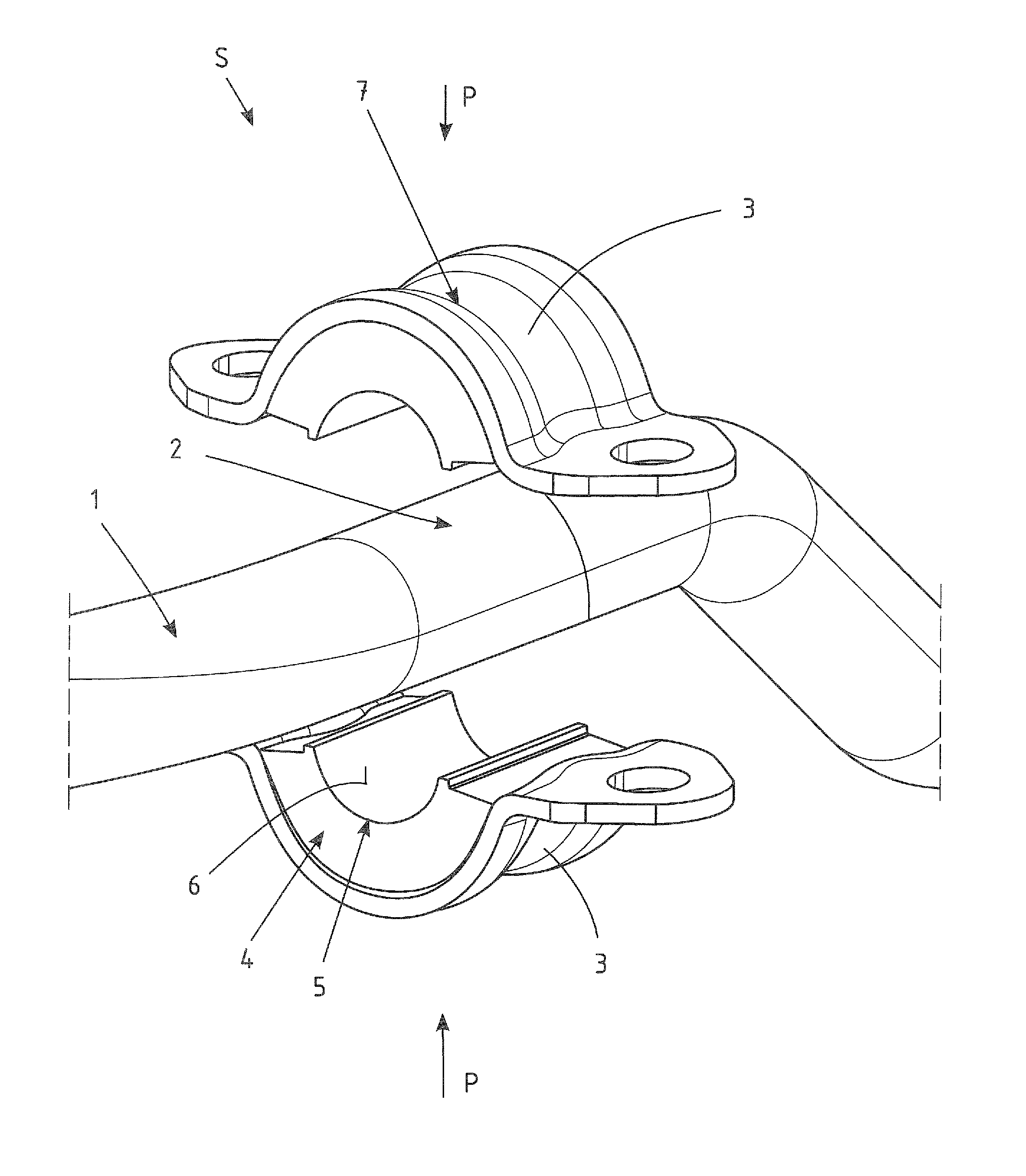
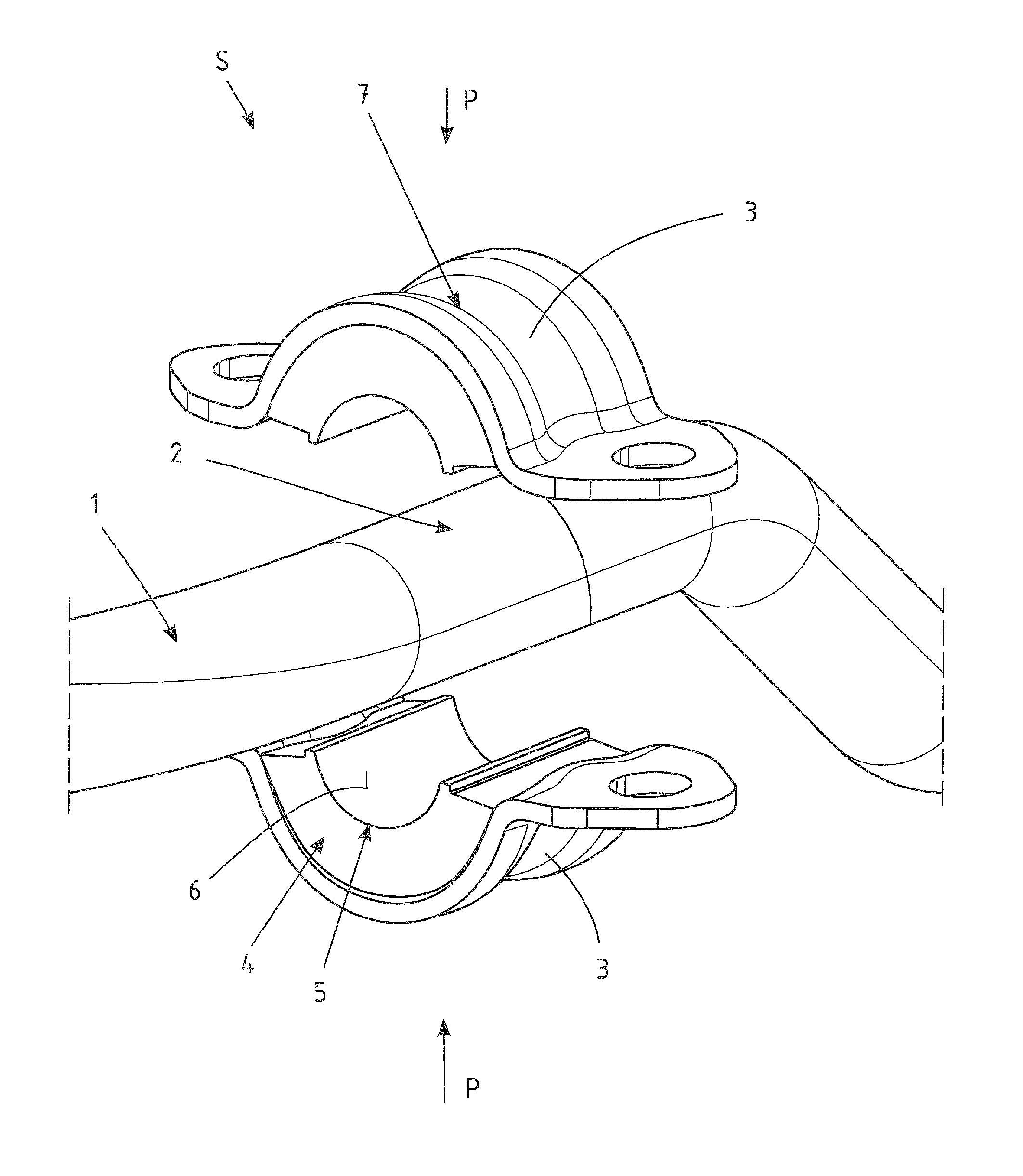
[0022]Turning now to FIG. 1, there is shown an exploded view of a stabilizer, generally designated by reference numeral 1 in an area of a stabilizer bearing. The stabilizer 1 has a stabilizer bearing portion 2 which is produced by a method in accordance with the present invention, involving a chemical pretreatment of the stabilizer bearing portion 2. Chemical pretreatment may involve abrasive treatment and optionally a cleaning e.g. by means of an alcohol-containing or acetone-containing cl...


PUM

PropertyMeasurementUnit
tensionaaaaaaaaaa
widthaaaaaaaaaa
areaaaaaaaaaaa

Abstract

In a method of producing a stabilizer for a motor vehicle, a stabilizer bearing portion of a stabilizer is chemically pre-treated by applying an adhesive. The stabilizer and two vulcanized elastomer-metal bearing half-shells are then placed in a joining apparatus for subsequent bonding of the bearing half-shells with the stabilizer bearing portion.

Description

CROSS-REFERENCES TO RELATED APPLICATIONS[0001]This application claims the priority of German Patent Application, Serial No. 10 2010 033 036.1, filed Aug. 2, 2010, pursuant to 35 U.S.C. 119(a)-(d), the content of which is incorporated herein by reference in its entirety as if fully set forth herein.BACKGROUND OF THE INVENTION[0002]The present invention relates to a method of producing a stabilizer with a stabilizer bearing for use in a motor vehicle.[0003]The following discussion of related art is provided to assist the reader in understanding the advantages of the invention, and is not to be construed as an admission that this related art is prior art to this invention.[0004]Stabilizers in the automobile construction involve torsion spring bars to stabilize the vehicle body against tilt and twist, when the motor vehicle travels in a curve. In addition, stabilizers are provided for wheel load compensation, for example when traveling in curves or also when driving over an obstacle or ...

Claims


Application Information

Patent Timeline
Patent Type & Authority Patents(United States)
IPC IPC(8): B60G11/18
CPCB60G21/0551B29C65/48B29C66/1122B29C66/532B29C66/71B29C66/742F16F1/3842Y10T156/1089B60G2206/821B29L2031/04B29L2031/721B29C65/4835B29C65/542F16B11/006B29C65/522B29L2031/3055B60G2204/1222B29K2021/00B29C66/73161
Inventor GRUNDMEIER, GEORG
Owner BENTELER AUTOMOBILTECHNIK GMBH
Why Eureka
Try Eureka