Linear drive for sliding doors or the like

a technology of sliding doors and drives, applied in the field of linear drives, can solve the problem of almost impossible monitoring of the closing edges of the movable panel, and achieve the effects of slowing down the movable panel, reducing the risk of damage, and increasing the safety of operation

Active Publication Date: 2013-06-04
DORMAKABA DEUT GMBH
View PDF11 Cites 0 Cited by
  • Summary
  • Abstract
  • Description
  • Claims
  • Application Information

AI Technical Summary

Benefits of technology

[0013]According to one embodiment the invention, the control circuit, by monitoring predetermined parameters, is furthermore preferably adapted to detect a presence of possible obstacles on the travel path of the at least one panel. The parameters may comprise a travel speed of the at least one panel, a position of the at least one panel and / or a driving current of the linear motor driving this panel. This allows for example to detect malfunctioning and to take necessary countermeasures, thus increasing the safety of operation.
[0014]The control circuit is furthermore preferably adapted to allow for displacing the at least one panel, independently from the linear motor, i.e. manual displacing up to a predetermined maximum travel speed of the at least one panel. When an excess of the maximum travel speed is determined, the control circuit is able to operate the linear motor in a direction opposite to the current travel direction of the at least one panel, with a predetermined driving force which depends on a measure of excess of the maximum travel speed. This means, the movable panel can only be displaced up to a predetermined maximum speed. This serves to protect rotor rollers against excessive mechanical stress and thus against premature wear or even against damages. Preferably this type of operating the linear motor is performed by switching-off, generative operating and / or driving the linear motor in a direction opposite to the current travel direction of the at least one panel. The possibility is thereby provided to prevent possible excessively high motor currents and to protect the sliding door against damage. In addition, it is possible to slow down the movable panel from a speed in the area of a limit stop to such an extent that a risk of damages is reduced.
[0015]The control circuit is furthermore preferably adapted, during a driving operation of the at least one panel when reaching a predetermined braking area with regard to the at least one panel, to drive the linear motor according to a predetermined braking behaviour. Preferably, there are two braking areas, namely respectively in front of a limit stop of the at least one panel. These braking areas serve to safely slow down the movable panel.
[0016]The control circuit, in at least one terminal position of the at least one panel, is furthermore preferably adapted to control the linear motor such that the at least one panel, with a predetermined force, is prevented from moving against the movement of the at least one panel out of the respective terminal position. Preferably, this operation is performed by controlling the linear motor in at least one terminal position of the at least one panel such that the panel maintains its position. This serves to prevent the panel from an unwanted movement, for example on account of wind-induced influences.
[0017]It is furthermore preferred that the linear drive has a sensor system for monitoring parameters relevant for a smooth operation of the linear drive. These operating parameters comprise for example an operating temperature of the linear motor and / or of the control circuit and / or of a power supply unit of the linear motor. The control circuit, upon detecting that at least one of the operating parameters is outside a predetermined, admissible range, is preferably adapted to control the linear drive in an altered manner. The change may reduce a driving speed of the linear motor, extend an opening or closing stop time with regard to the at least one panel, and / or switch off the linear drive. This will serve the purpose of allowing the linear drive (time wise) to cool down, something that would perhaps not be possible in an otherwise normally continued operation.

Problems solved by technology

The minimum travel speed is provided, because it is almost impossible to monitor the closing edges of the movable panel during the learning run.

Method used


Image

  • Linear drive for sliding doors or the like
  • Linear drive for sliding doors or the like
  • Linear drive for sliding doors or the like

Examples


Embodiment Construction

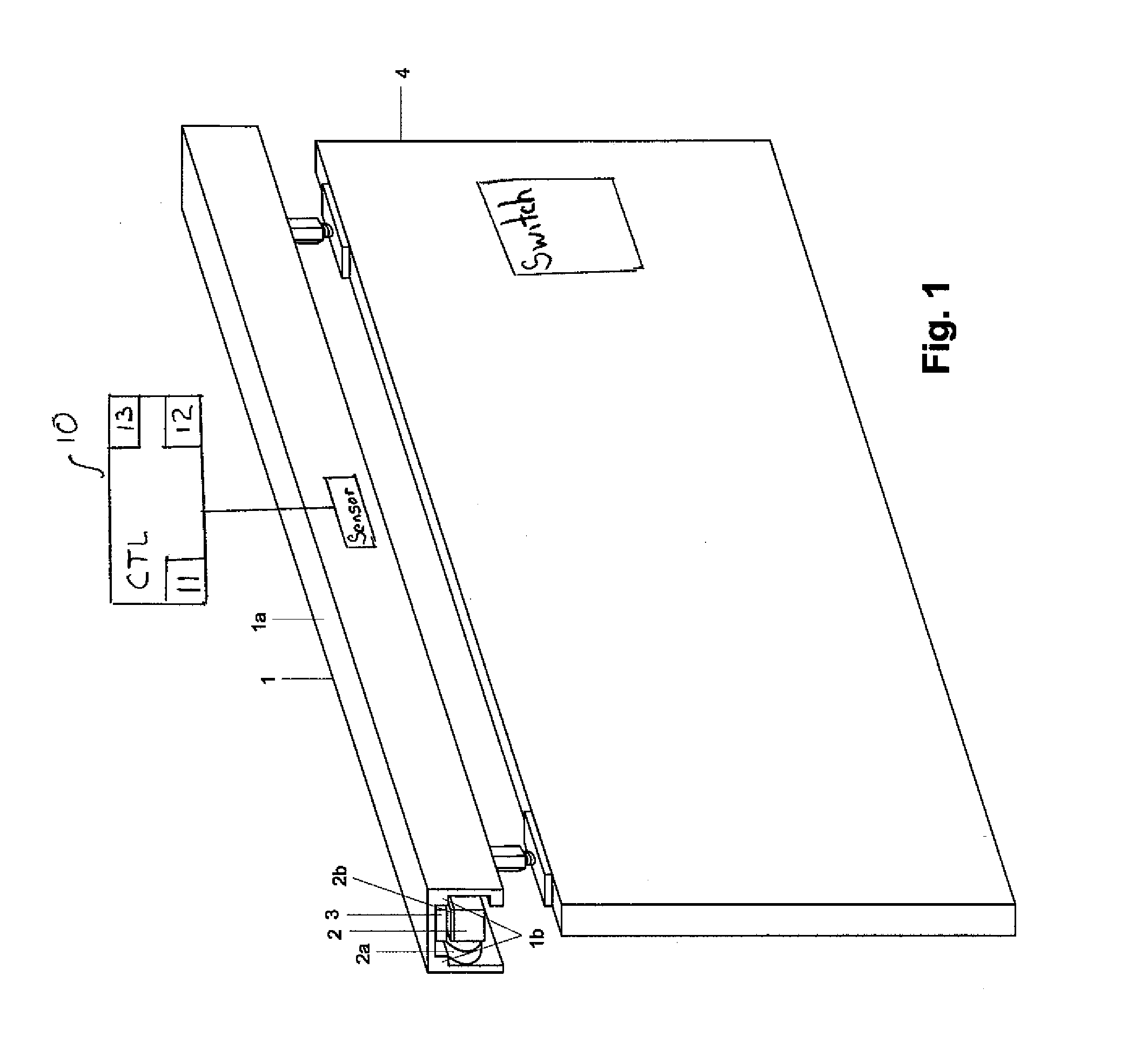
[0024]The installation shown in FIG. 1 comprises a linear drive 1, which, in the example shown, has a carrying profile 1a. At an interior surface of the carrying profile 1a, pointing downwards in FIG. 1, guiding rails 1b are configured, respectively disposed preferably at both sides in cross-section.

[0025]Furthermore, in the example shown, the installation comprises a panel configured as a sliding door leaf 4, movable along a travel path. The travel path is defined by a course of the guiding rails 1b.

[0026]At the inner side of the carrying profile 1a, a stator member 3 is preferably disposed between the guiding rails 1b. As an alternative, the guiding rails 1b can be formed by the interior surface itself, as long as the latter has a sufficient stability.

[0027]Preferably, the stator member 3 has a row of electrical coils extending along at least one portion of the travel path, which are interconnected according to a predetermined control scheme, preferably a 3-phase control scheme. ...


PUM


Abstract

A linear drive based on linear motors, for panels, in particular sliding doors, movable along a respective travel path. A linear drive for at least one panel, in particular a sliding door leaf, movable along a travel path, has at least one linear motor for this at least one panel. The linear motor is provided with a stator member and a carriage. Furthermore, the linear drive has a control circuit. The control circuit is adapted to stop the linear motor in the event of failure of power supply to the linear motor, by switching-off the linear motor and operating it as a generator. Thereupon, in terms of its displaceability, this movable panel is enabled by the control circuit. In addition, the linear drive has a switch for switching-off the energy supply to the at least one linear motor.

Description

PRIORITY CLAIM[0001]This is a U.S. national stage of application No. PCT / EP2008 / 005906, filed on Jul. 18, 2008 which claims priority to the German Application No.: 10 2007 038 844.8, filed: Aug. 16, 2007, the content of both incorporated herein by reference.BACKGROUND OF THE INVENTION[0002]1. Field of the Invention[0003]The invention relates to linear drives, which are based on linear motors, for panels, in particular sliding doors, movable along a respective travel path.[0004]2. Related Art[0005]Sliding doors operated by linear motors are well known. Usually a stator, which essentially consists of a row of interconnected electrical coils, is disposed above a respective sliding door leaf in a stationary part. At a side facing the stator, the respective sliding door leaf is provided with a rotor, which has a row of one of permanent magnets and / magnetizable material.SUMMARY OF THE INVENTION[0006]An object of invention is to further develop the functionality of linear drives based on l...

Claims


Application Information

Patent Timeline
Patent Type & Authority Patents(United States)
IPC IPC(8): F04D15/00E05F15/60
CPCE05F5/003E05F15/60E05Y2900/132
Inventor BUSCH, SVEN
Owner DORMAKABA DEUT GMBH
Why Eureka
Try Eureka