
Optical proximity switch

a proximity switch and optical technology, applied in the direction of resistors with sliding contact, resistors with adjustable contact, pulse technique, etc., can solve the problems of increasing not only the production cost but also the operating cost, putting a thermal burden on the device as well as the disadvantage of the lack of a display unit, etc., and achieves high precision

Active Publication Date: 2013-06-04
IMF ELECTRONIC GMBH
View PDF5 Cites 6 Cited by
  • Summary
  • Abstract
  • Description
  • Claims
  • Application Information

AI Technical Summary

Benefits of technology

The optical proximity switch described in this patent allows for precise adjustment of the switching point through a multi-turn potentiometer, which is supported for rotation and can be set without aids. The switch is connected to a crosswheel and a cam drive, making it easy to control. The switch is ideal for applications that require adjustable fading out of background. It can be used with various types of proximity switches, such as inductive, capacitive, or magnetic switches, as long as they have a multi-turn potentiometer for setting the switching interval. Overall, the switch provides a convenient and efficient solution for setting and controlling proximity switches.

Problems solved by technology

Self-illuminating LEDs and / or passive LCD displays increases not only the production costs but also the operating costs and put a thermal burden on the devices as well.
Its lack of a display unit is a disadvantage.

Method used


Image

  • Optical proximity switch
  • Optical proximity switch
  • Optical proximity switch

Examples


Embodiment Construction

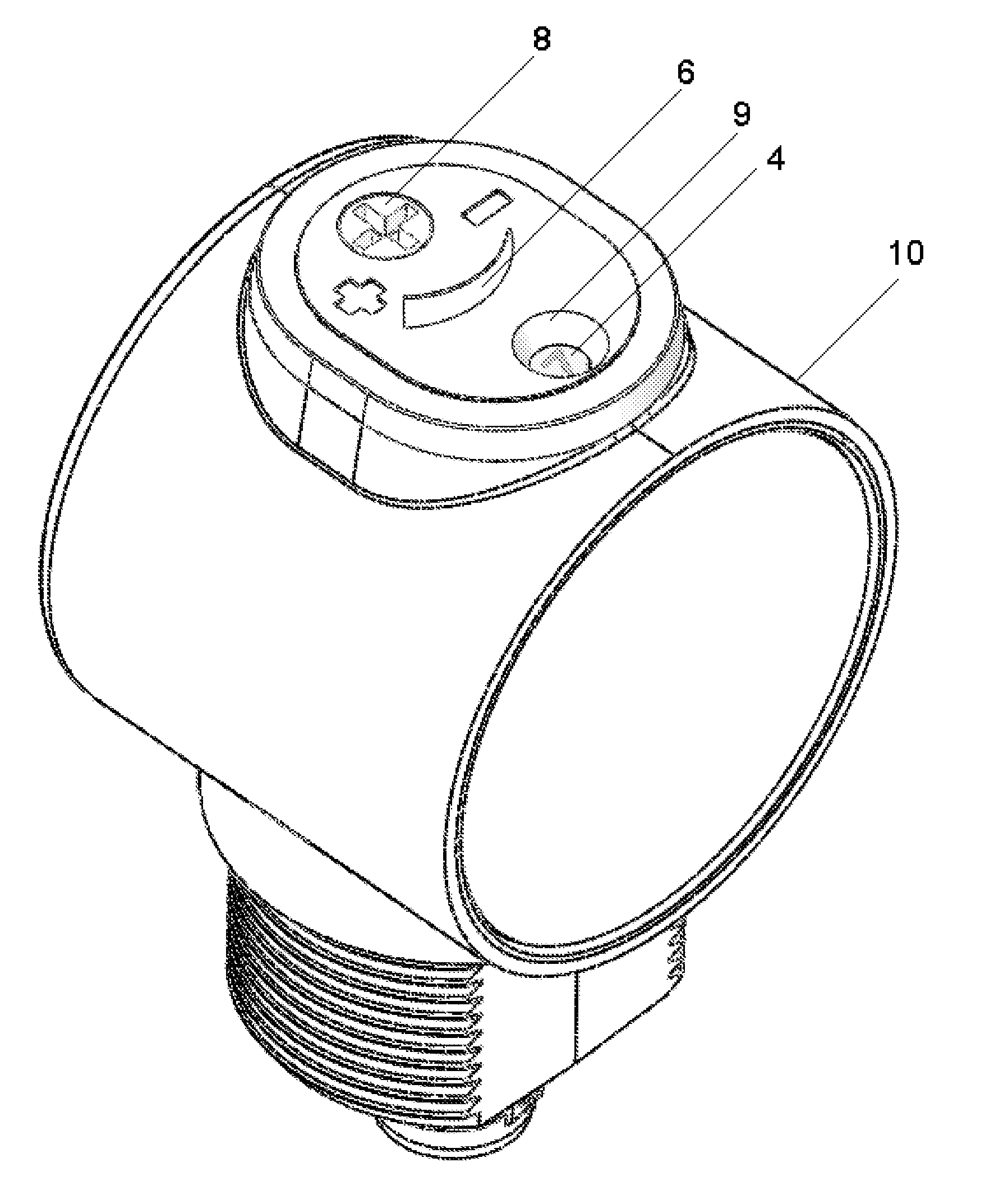
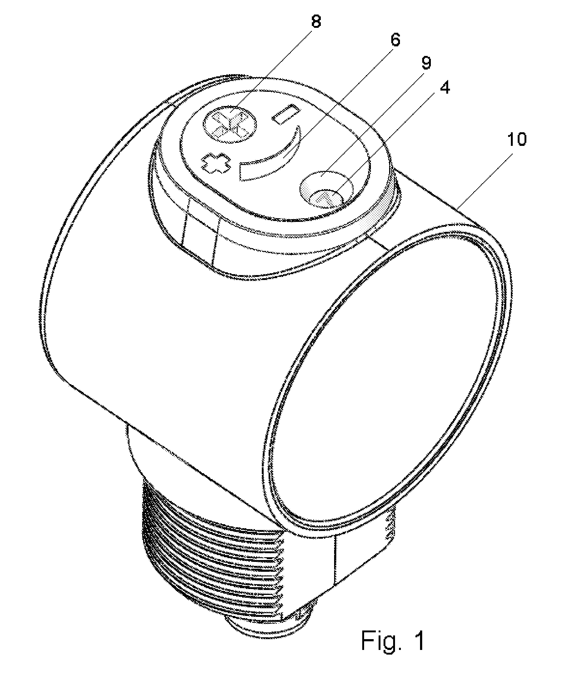
[0022]FIG. 1 shows an optical proximity switch assembly, in which the setting and display unit is located on the top side of a housing 10. FIGS. 1, 2 and 3 show a crosswheel 3 located behind a view port 9. A position index 4 is carried on the crosswheel 3 and is visible to the user through the view port 9. A rotation direction indicator 6 and a slot 8, adapted to receive the tip of a screw driver, are also shown.

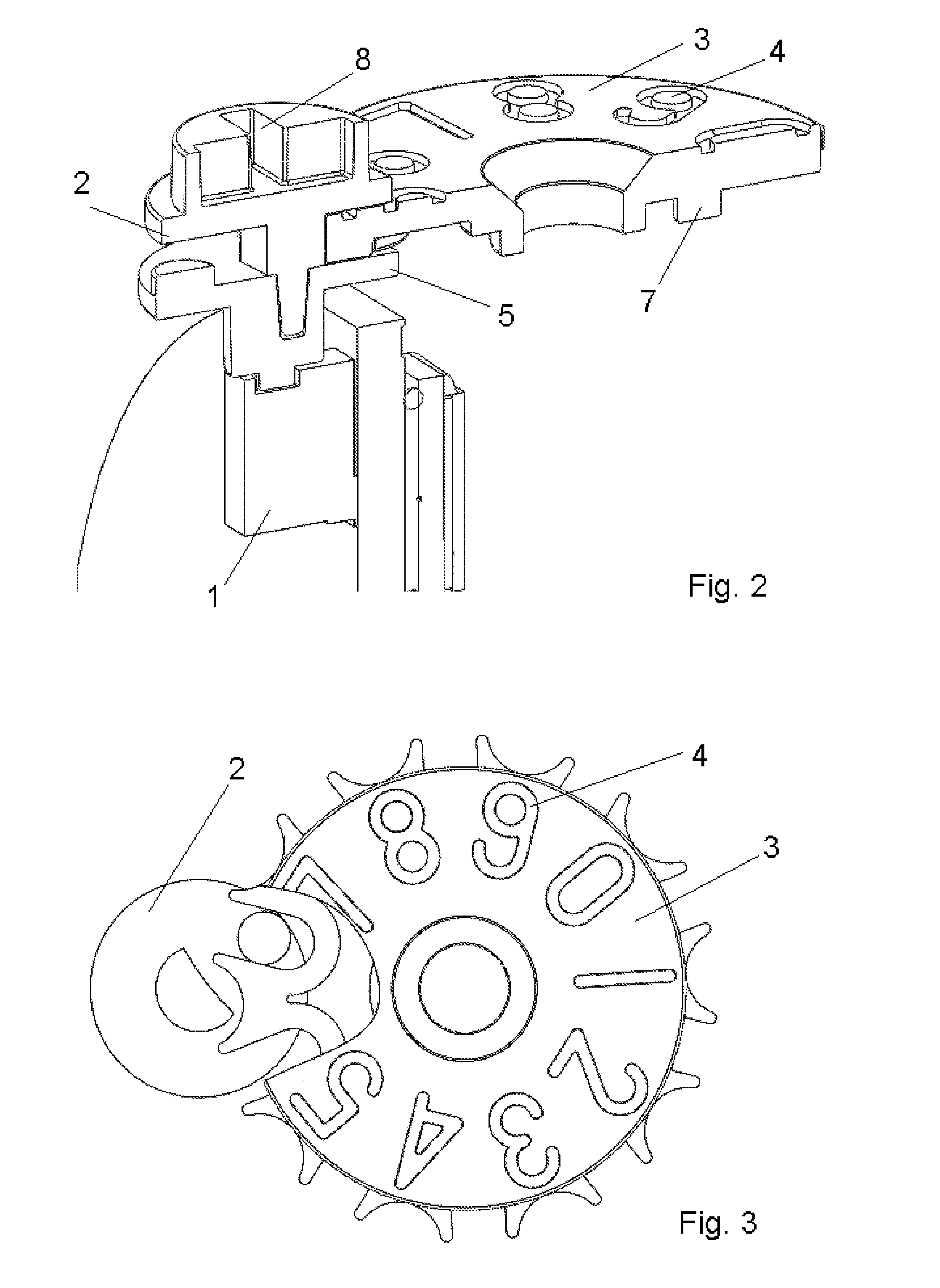
[0023]FIG. 2 shows, in a sectional view, details of the internal structure of the switch assembly, which includes a multi-turn potentiometer 1, cam drive 2, and the crosswheel 3.

[0024]The top side of the crosswheel 3 is labeled with numbers of the position index 4, each number representing the variable angular position of the crosswheel 3, each number becoming visible to the user as the crosswheel 3 rotates position index 4. In FIG. 1, number “7” of the position index 4 is visible to the user through view port 9.

[0025]User operation is effected via the screwdriver slot 8 on ...


PUM


Abstract

An optical proximity switch includes a potentiometer for setting a switching point and supported for rotation through multiple turns, a crosswheel supported for rotation and including a visible position index visible, and a cam drive rotatably coupled to the potentiometer and the crosswheel.

Description

BACKGROUND OF THE INVENTION[0001]1. Field of the Invention[0002]This invention relates generally to an optical proximity switch, particularly to adjusting the setting of a potentiometer.[0003]2. Description of the Prior Art[0004]Optical proximity switches are used as contactless electronic switches for monitoring purposes. They are used also in the automation industry.[0005]Optical proximity switches include an optical transmitter; usually an LED or laser diode, for transmitting a light signal to a monitoring area; and at least one photodetector for receiving the light signal transmitted. If an object is located in the monitoring area, the light signal is interrupted or reflected, at least it is attenuated or its polarization direction changes. If the influence of the object on the light signal reaches a degree determined by a switching threshold, then a switching signal is tripped.[0006]Switchgear of this kind is produced and sold in various embodiments and is commercially availabl...

Claims


Application Information

Patent Timeline
IPC IPC(8): H01C10/50
CPCH01C10/50H03K2217/94021
Inventor VINSHTOK, YEVGENIYBREH, PETER
Owner IMF ELECTRONIC GMBH
Learn More