
Three dimensional radar method and apparatus

a three-dimensional radar and three-dimensional technology, applied in the direction of leaky-waveguide antennas, instruments, antennas, etc., can solve the problems of over $2 billion in annual cost to military and commercial aviation, nearly 200 people have been killed or injured, and daily collisions of birds with planes

Inactive Publication Date: 2013-06-04
PIESINGER GREGORY HUBERT
View PDF20 Cites 30 Cited by
  • Summary
  • Abstract
  • Description
  • Claims
  • Application Information

AI Technical Summary

Benefits of technology

The present invention is a radar system for detecting avians (especially poultry) on an airport. A bistatic radar receiver is located on the airport and multiple bistatic transmitters are placed around the airport. The transmitters illuminate the avians and the reflected signals are received by the bistatic radar receiver. The location of the avians is determined based on the known locations of the transmitters, receiver, and the measured transmitter signal ranges. This system is similar to GPS in determining target position accuracy. The bistatic radar receiver antenna is composed of a vertical array of elements which can electronically scan in elevation and form multiple narrow beams. Coherent processing can be provided on some or all formed beams to obtain Doppler target information. The system can track targets as they move through the coverage area and identify them based on their reflectivity, altitude, velocity, spectral width, and track patterns. This invention can provide a reliable and efficient means of detecting avians on airports and preventing them from causing damage or spreading disease.

Problems solved by technology

Aviation experts say bird-plane collisions happen daily.
Nearly 200 people have been killed or injured since 1990 in accidents involving aircraft and wildlife.
It is estimated that bird strikes cost military and commercial aviation over $2 billion each year due to damage and other costs.
However, outside of these few major airports, no bird detection devices are currently available other than the pilot's see-and-avoid procedures.
Many azimuth rotations must be made to obtain a full elevation scan which takes considerable time.
This results in a slow coverage volume update rate and poor bird tracking performance.
However, these radars are far too expensive for use as avian radars.
However, without real-time precise positional and altitude information, current avian radars cannot be used to issue specific bird strike collision warnings or to alter air operations based on imminent bird collision threats.

Method used


Image

  • Three dimensional radar method and apparatus
  • Three dimensional radar method and apparatus
  • Three dimensional radar method and apparatus

Examples


Embodiment Construction

[0026]The goal of the present invention is to provide a low cost avian radar with very advanced features. The radar's primary feature is precise target height determination because aircraft danger from birds primarily depends on bird altitude. Birds far below or above an aircraft pose no danger to the aircraft even if both the bird and aircraft occupy the same 2D range / azimuth position on a radar display. The height resolution of most current avian radars is on the order of 1000 feet at ranges greater than about 1 km. Therefore, there is currently no way to determine if birds and aircraft displayed on a collision course are actually a threat when using a 2D display.

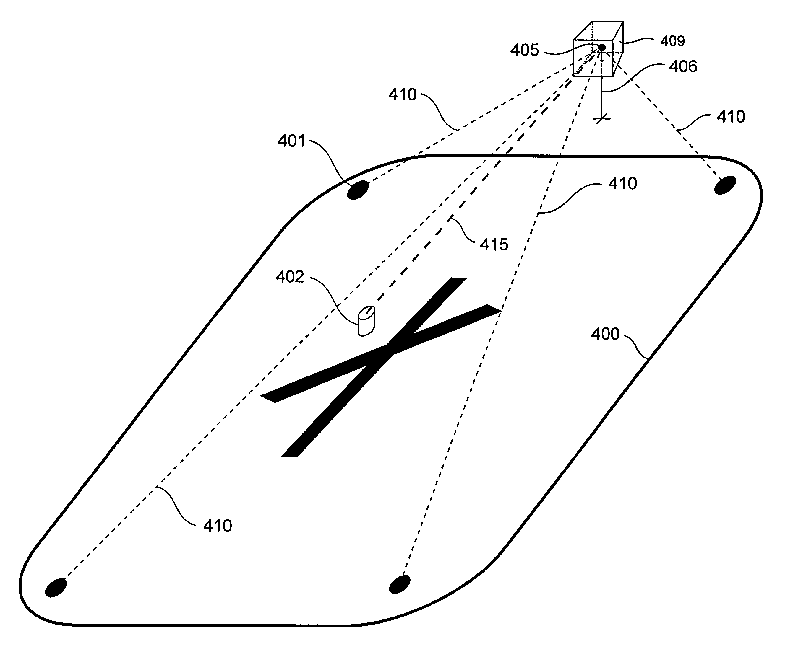
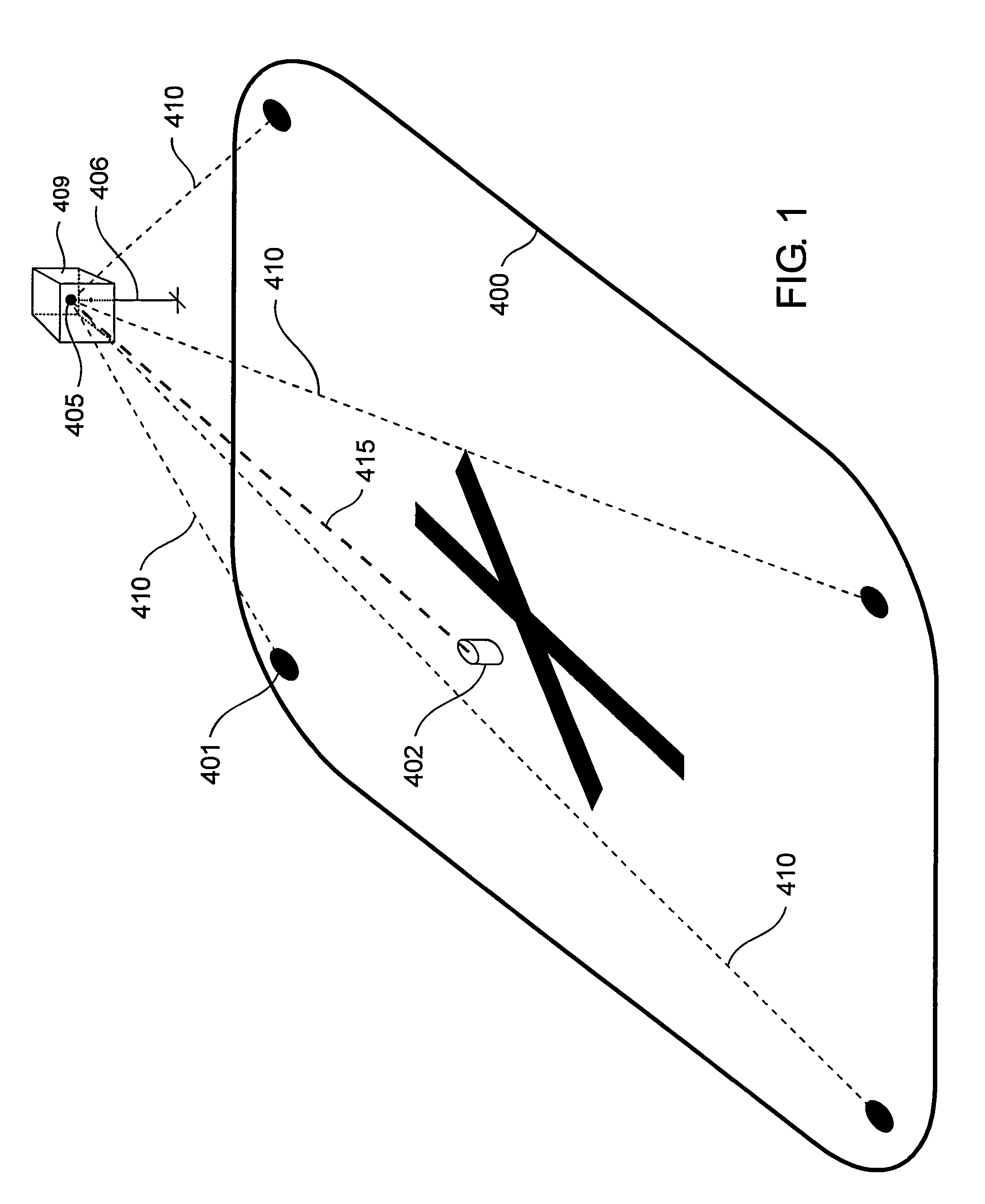
[0027]FIG. 1 illustrates 4 bistatic transmitters 401 deployed around airport perimeter 400. Bistatic receiver 402 is positioned near the airport center. Avian target 405 is somewhere within the design range of the bistatic transmitter array. Bistatic transmitter signals 410 illuminate target 405 at height 406 and their re...


PUM


Abstract

A bistatic radar receiver is centrally located within an array of multiple bistatic transmitters at an airport to precisely determine bird positions and altitudes. Bird target reflections from multiple transmitters are received by the radar receiver. Target location is determined by the transmitter location, receiver location, and measured transmitter-to-target-to-receiver ranges. Target position and altitude accuracy is similar to GPS. The radar receiver antenna is composed of a vertical array of elements and rotated 360 degrees in azimuth. The output of each element is downconverted, digitized, and digitally beamformed to provide multiple simultaneous antenna beams each electronically scanned in elevation. When bistatic transmitters cannot be deployed, a narrow-azimuth wide-elevation transmit antenna beam is overlapped with a wide-azimuth narrow-elevation receive antenna beam electronically scanned in elevation to provide a composite narrow azimuth and elevation beamwidth.

Description

RELATED INVENTION[0001]The present invention claims priority under 35 U.S.C. §119(e) to: “3D Radar Method and Apparatus” Provisional U.S. Patent Application Ser. No. 61 / 210,487, filed 19 Mar. 2009, and to: “Aircraft Bird Strike Avoidance Method and Apparatus using Transponder or Pseudolites” Provisional U.S. Patent Application Ser. No. 61 / 211 / 409, filed 30 Mar. 2009 which are incorporated by reference herein.TECHNICAL FIELD OF THE INVENTION[0002]The present invention relates to the field of three dimensional (3D) radar. More specifically, the present invention relates to the field of 3D avian radar for detecting, determining height, and tracking birds.BACKGROUND OF THE INVENTION[0003]Aviation experts say bird-plane collisions happen daily. Nearly 200 people have been killed or injured since 1990 in accidents involving aircraft and wildlife. It is estimated that bird strikes cost military and commercial aviation over $2 billion each year due to damage and other costs. Most birds fly ...

Claims


Application Information

Patent Timeline
IPC IPC(8): G01S13/93
CPCG01S13/46G01S13/003G01S13/88G01S13/426H01Q3/04H01Q13/22H01Q21/061G01S13/06G01S2013/468G01S13/91G01S13/93
Inventor PIESINGER, GREGORY HUBERT
Owner PIESINGER GREGORY HUBERT
Learn More