Image coding apparatus, control method thereof, and storage medium

a coding apparatus and image technology, applied in the field of image data coding technique, can solve the problems of increasing the processing time of code concatenation and the apparatus cannot benefit from the effect of encoding, and achieve the effect of reducing the influence of the number of syntax elements

Inactive Publication Date: 2013-06-04
CANON KK
View PDF3 Cites 1 Cited by
  • Summary
  • Abstract
  • Description
  • Claims
  • Application Information

AI Technical Summary

Benefits of technology

[0011]The present invention has been made in view of the above-described problem. The present invention provides an image coding technique, which can reduce influence of the number of syntax elements and realize high-speed encoding, even in a case where there are a plurality of syntax elements.
[0013]According to the present invention, it is possible to further reduce time which is necessary for generating a code stream for a block, constituting an image, based on a transform coefficient obtained by performing frequency transformation on the block, and realize high-speed encoding.

Problems solved by technology

However, the image coding apparatus according to the conventional art has a problem in that processing performance of the apparatus depends upon the number of syntax elements. FIG. 3A shows a code storing method of each variable-length code storage unit, which constitutes the N number of variable-length code storage units 204-1 to 204-N.
As described above, if the conventional art is applied to the JPEG XR coding scheme for encoding a large number of syntax elements, processing time for code concatenation increases, and thus the apparatus cannot benefit from the effect of encoding.

Method used


Image

  • Image coding apparatus, control method thereof, and storage medium
  • Image coding apparatus, control method thereof, and storage medium
  • Image coding apparatus, control method thereof, and storage medium

Examples


first embodiment

[0031]As an industrially applicable form of the present embodiment, first described is an image processing apparatus having a function for encoding an image and decoding the encoded image. Typical images subjected to encoding include an image read out of an image sensor of a digital camera or a digital camcorder, or an image received through a network. For a typical apparatus, a digital camera or the like may be given as an example.

[0032]Hereinafter, a digital camera having a configuration shown in FIG. 4 is described as an example. An image of an image-capturing target is formed on an image sensor 402, such as CCD, CMOS sensor or the like, through a lens 401. The image sensor 402 converts the formed image to an analog signal, and transmits the analog signal to an A / D converter 403. The A / D converter 403 converts the analog signal, which has been received from the image sensor 402, to a digital signal. A memory controller 407 acquires, from the A / D converter 403, the converted digit...

second embodiment

[0071]Next described as a second embodiment is a case where the present invention is applied to entropy coding according to the JPEG XR coding scheme.

[0072]According to entropy coding of the JPEG XR coding scheme, a transform coefficient on which coefficient prediction has been performed is divided into higher-bit data and lower-bit data. While variable-length coding is performed on the higher-bit data, the lower-bit data is processed (fixed-length coding) as fixed-length data (is also referred to as a fixed-length code, FLEXBITS). In the JPEG XR coding scheme, a MB is further divided into smaller blocks, and coding is performed in units of these blocks (FIG. 12). Further, code streams are defined (FIG. 13) for alternately inserting a variable-length code (VLC in FIG. 13) and a fixed-length code (FLC in FIG. 13) in block unit (Block in FIG. 13).

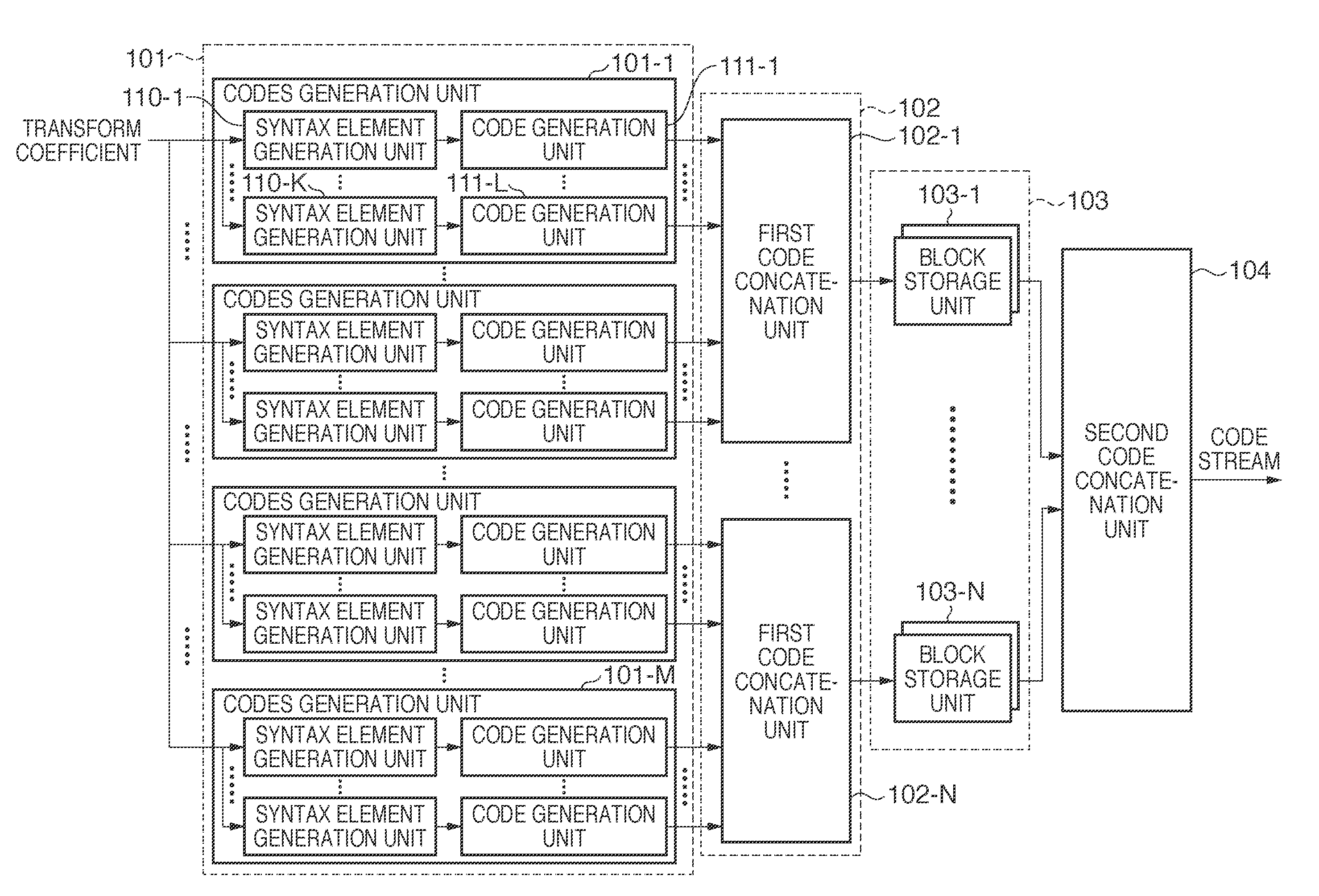
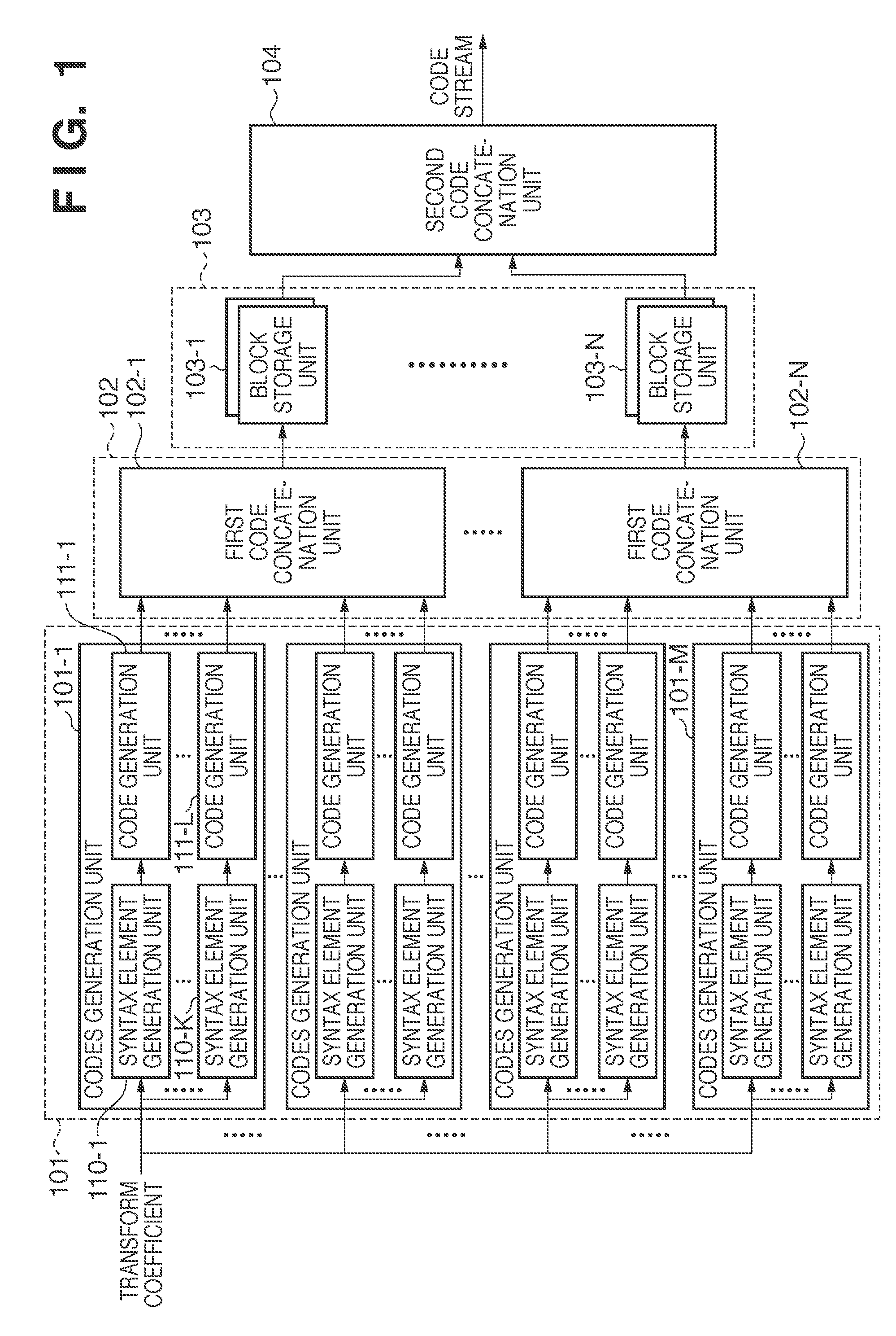
[0073]The second embodiment is shown in FIG. 9. The second embodiment has a configuration of FIG. 1, where M=4 and N=2. The four codes gener...


PUM


Abstract

Even in a case where there are a plurality of syntax elements, the invention reduces influence of the number of syntax elements and realizes high-speed encoding. An apparatus comprises N number of codes generation units arranged in parallel, which are configured to generate codes, including one or more codes, based on a transform coefficient; N number of first code concatenation units arranged in parallel, each of which is configured to concatenate the codes, respectively generated by the N number of codes generation units, for generating a code stream; N number of storage units arranged in parallel, each of which is configured to store the N number of code streams inputted from the N number of first code concatenation units; and a second code concatenation unit configured to read each of the code streams, which are stored in the N number of storage units, and concatenate the read code streams.

Description

BACKGROUND OF THE INVENTION[0001]1. Field of the Invention[0002]The present invention relates to an image data coding technique.[0003]2. Description of the Related Art[0004]In still-image and moving-image encoding, generally, image data is divided into rectangular tiles of a predetermined size, and each of the tiles is further divided into a plurality of macro blocks (MB) of a predetermined size. With the MB as a processing unit of encoding, data constituting the MB is subjected to orthogonal transformation, quantization, and coefficient prediction. After the coefficient prediction is performed, the data is further subjected to scan conversion for converting two-dimensional data to one-dimensional data consisting of a non-zero coefficient (non-zero data) and an zero coefficient (zero data), that is, a coefficient having zero run length. Based on one-dimensional data which has been rearranged in the foregoing manner, a plurality of syntax elements are generated, and each of the synta...

Claims


Application Information

Patent Timeline
Patent Type & Authority Patents(United States)
IPC IPC(8): G06K9/36H04N19/60H03M7/30H04N1/41H04N19/102H04N19/136H04N19/423H04N19/503H04N19/593H04N19/61H04N19/93
CPCH04N19/176H04N19/436H04N19/91H04N19/60
Inventor KIMURA, MAKOTO
Owner CANON KK
Why Eureka
Try Eureka