Coupling device for coupling containers, particularly containers used in cargo ships

a technology for coupling containers and coupling parts, which is applied in the direction of containers, flexible elements, transportation items, etc., can solve the problems of permanent changes in corner pieces, coupling pieces, and unreliable operation of coupling parts

Inactive Publication Date: 2013-06-11
CARGOTEC FINLAND
View PDF12 Cites 11 Cited by
  • Summary
  • Abstract
  • Description
  • Claims
  • Application Information

AI Technical Summary

Benefits of technology

[0010]By means of this now described invention, a novel kind of a coupling device is provided for coupling containers to each other, by which problems of known arrangements can be eliminated, and by which is indeed achieved a coupling device which is easy to use and reliable in use. By the coupling device, it is possible to couple the containers to each other such that they cannot unlock from each other unintentionally and that it operates effectively for receiving substantially vertical forces between the containers (and further forces in other directions) and, the containers being coupled, the coupling device well endures stresses directed to it. Furthermore, the arrangement according to the invention is relatively simple and inexpensive to manufacture.

Problems solved by technology

Because of this, their operation can be unreliable and even cause dangerous situations, because the locking of the coupling devices can fail due to forces caused by asymmetric lockings.
Already with safe loads, the lockings cause permanent changes in the corner pieces of the containers due to one-sided load distribution, and this is extremely disadvantageous.
If displacements in the coupling arrangements, i.e. the displacement of coupling arrangements when they are being fitted in the corner pieces of the containers, grow too great, then there is a risk that other than the coupling pieces, such as locking bars etc., receive too great forces and the system will overload.

Method used


Image

  • Coupling device for coupling containers, particularly containers used in cargo ships
  • Coupling device for coupling containers, particularly containers used in cargo ships
  • Coupling device for coupling containers, particularly containers used in cargo ships

Examples


Embodiment Construction

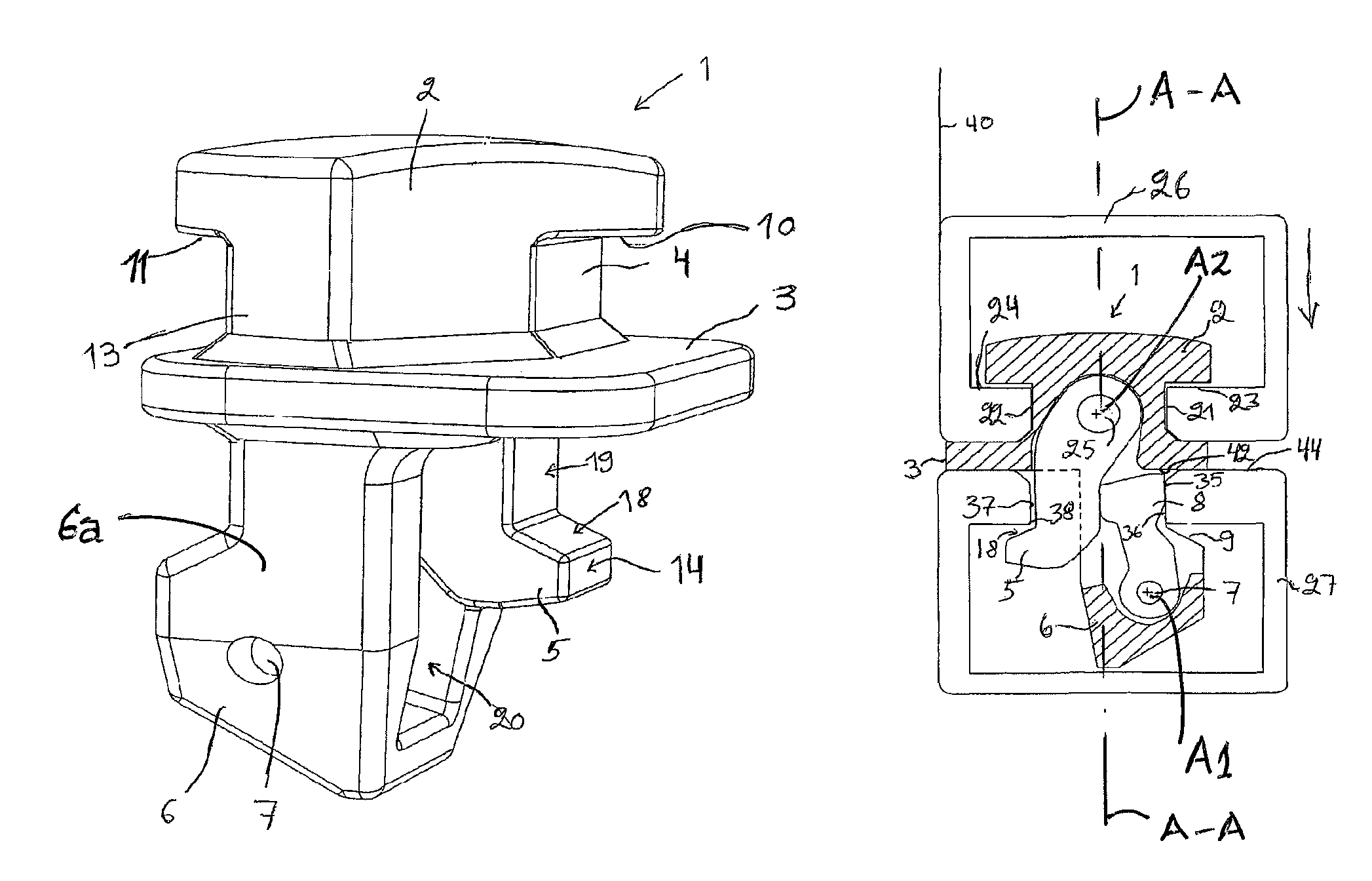
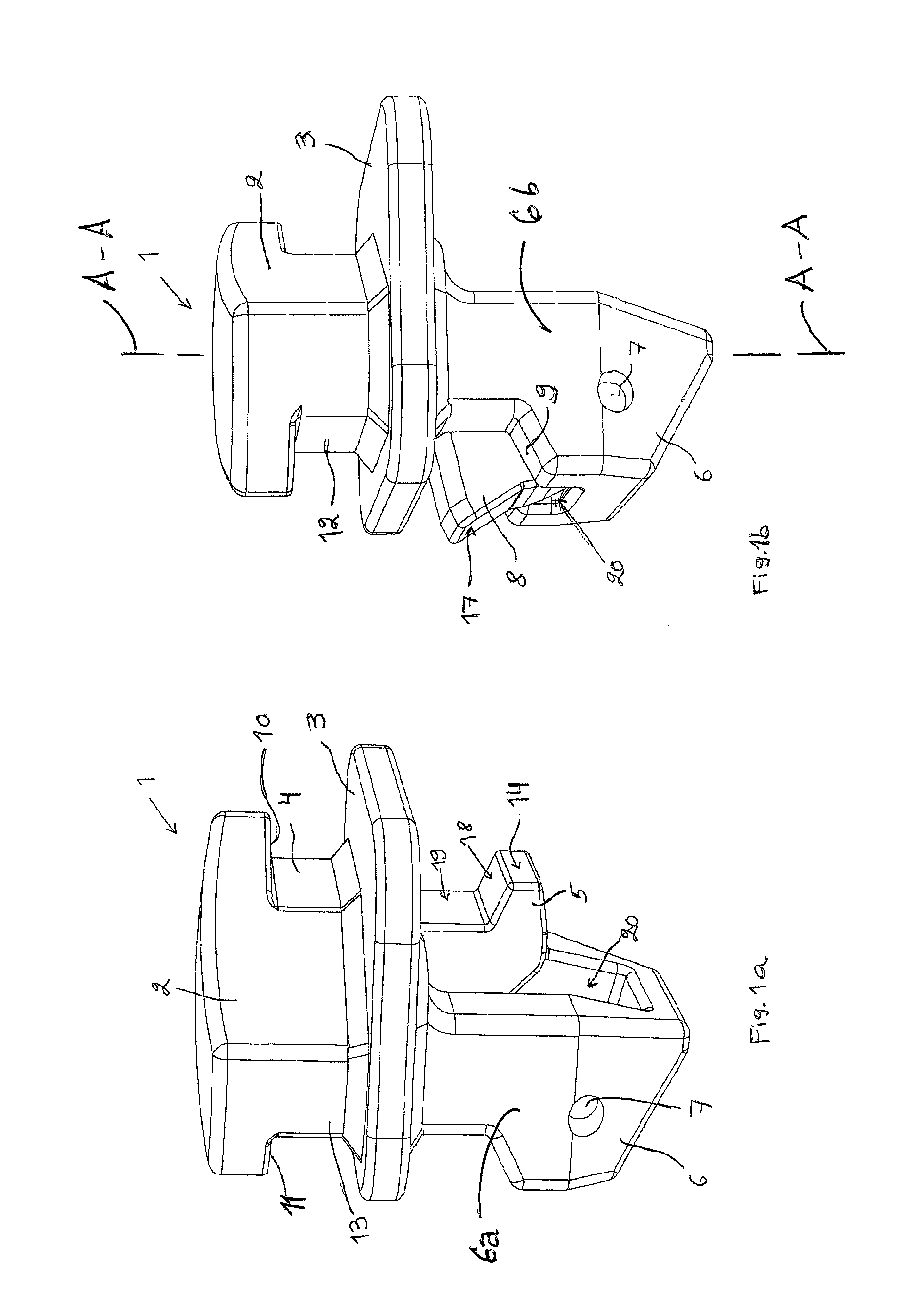
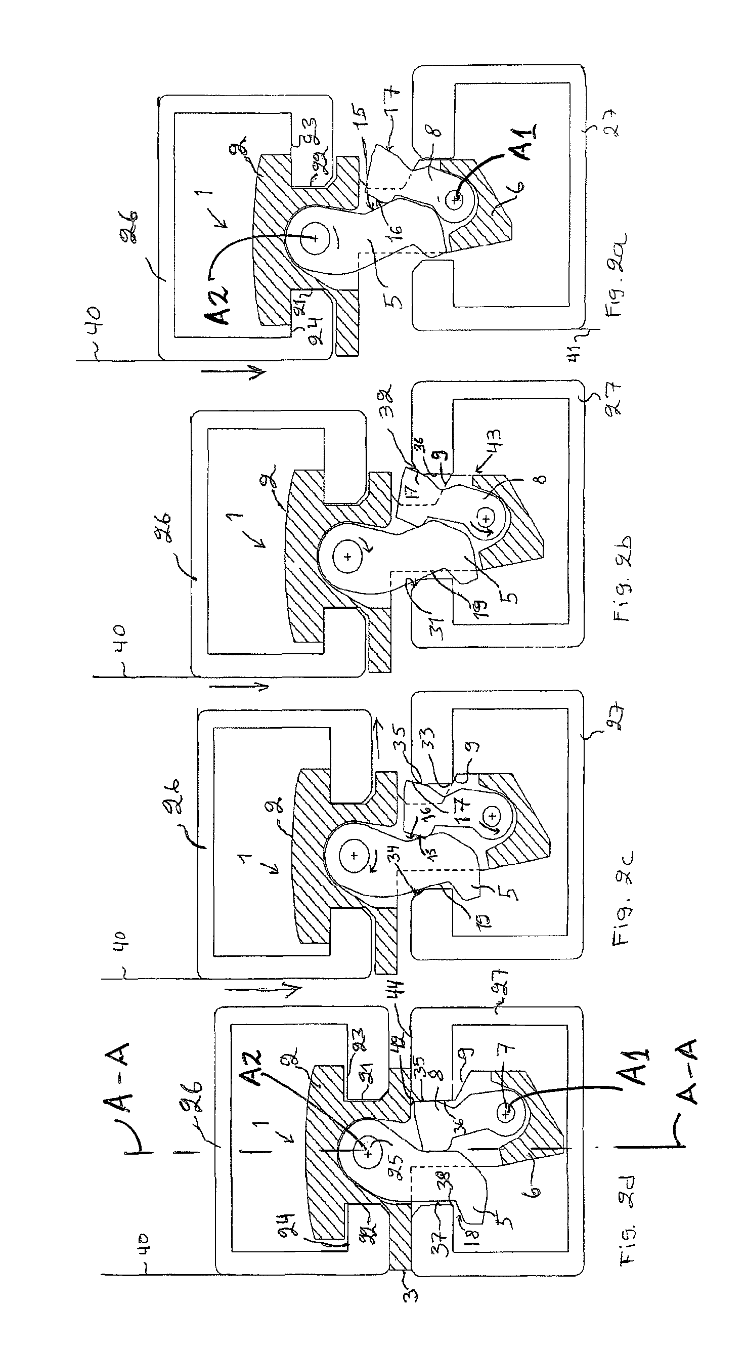
[0018]In accordance with FIGS. 1a and 1b, in a coupling device 1 according to the invention, there is in its body part 13 a fastening piece 2 formed in the upper part of the body part 13, by which the body part 13 is fastenable in a corner piece 26 in the corner of a container 40 (see FIGS. 2a, 4) by rotating the body part 2 around a vertical axis A-A thereof, whereby the fastening piece 2 fastens in the corner piece of the container 40, such that horizontal surfaces 10, 11 in the body part 13 receive vertical forces, and vertical surfaces 4, 12 in the body part 13 receive horizontal forces.

[0019]In the body part is formed between its upper part and lower part a planar coupling plate 3, which coupling plate sets between containers 40, 41 being lifted (FIG. 4), receiving forces between the containers, mostly the weight of the upper container 40, further the coupling plate receives and transfers friction forces which are produced of the weight of the containers when the containers 40,...


PUM


Abstract

A coupling device for coupling containers includes a body part having a fastening piece and a cam part on upper and lower parts thereof, and a planar coupling plate between the upper and lower parts. The fastening piece is fastenable to an upper corner piece in a corner of a container by rotating the body part around its vertical axis. The cam part controls the motion of the body part and receives substantially vertical forces between the containers. The body part includes a first rotating locking part for preventing and / or releasing the motion of the body part, and a second rotating locking part for enabling and / or preventing lateral motion of the body part. The second locking part is in direct or indirect contact with the first locking part so that when the first locking part rotates, the second locking part also rotates, enabling a locking mode or an unlocking mode.

Description

BACKGROUND OF INVENTION[0001]The invention relates to a coupling device according to the preamble of claim 1, which is used for coupling containers to each other, and particularly for coupling containers used in cargo ships to each other. In addition to sea transport, containers are also used for land transport.[0002]Conventionally when aboard ships, stacks formed by containers are able to tilt sideways, depending on the degree of the list of the ship. This means that at least two corners i.e. those of one or the other side of the container are under pressure caused by the mass of containers above them.[0003]On the other hand, when lifting containers, they are lifted so that all four corners are lifted up at the same time. For this reason, it is possible to distinguish clearly when the coupling devices of the containers have to be brought to a locking mode or an unlocking mode. In known arrangements, a vertical force, i.e. lifting force, is converted in the coupling device into a la...

Claims


Application Information

Patent Timeline
Patent Type & Authority Patents(United States)
IPC IPC(8): B60P7/13B65D90/00B63B25/00
CPCB60P7/132B63B25/004B65D90/0013Y10T24/28B65D2590/0033B61D5/08B60P7/13B63B25/00
Inventor OSTBERG, JUHANA
Owner CARGOTEC FINLAND
Why Eureka
Try Eureka