
Liquid jetting apparatus

a technology of liquid jetting apparatus and nozzle cap, which is applied in printing and other directions, can solve the problems of greatly impaired printing quality, inability to flow back toward the inside of the nozzle cap, etc., and achieve the effects of reducing waste of liquid, low cost, and easy manufacturing

Active Publication Date: 2013-06-11
BROTHER KOGYO KK
View PDF5 Cites 0 Cited by
  • Summary
  • Abstract
  • Description
  • Claims
  • Application Information

AI Technical Summary

Benefits of technology

The present invention provides a liquid jetting apparatus that can adjust the amount of liquid jetted during idle jetting for each liquid cartridge, based on their size and initial capacity. This helps to reduce the waste of liquid and prevents color mixture while flushing. It is not complicated to control and can be manufactured at low cost.

Problems solved by technology

However, after the vacuum pump is stopped, since the pressure in the ink-jet head is kept at the negative pressure though the negative pressure in the nozzle cap is released, there is a risk that the inks in the nozzle cap may flow back toward the inside of the nozzles.
When the mixed color ink is jetted at the time of the printing, printing quality is greatly impaired.

Method used


Image

  • Liquid jetting apparatus
  • Liquid jetting apparatus
  • Liquid jetting apparatus

Examples


first embodiment

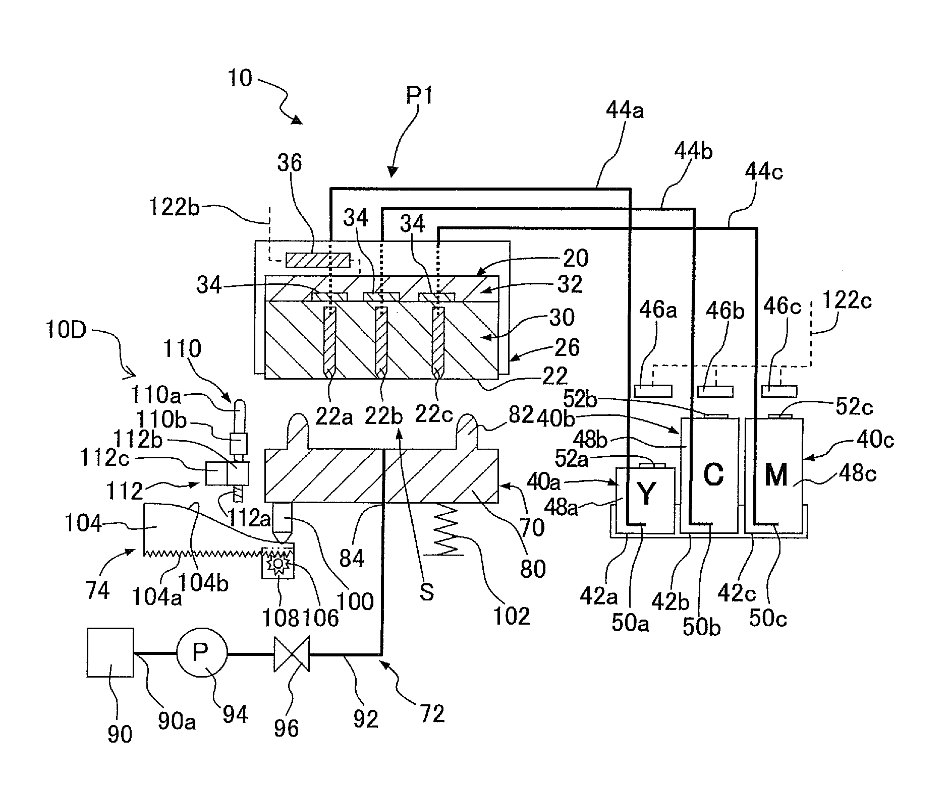
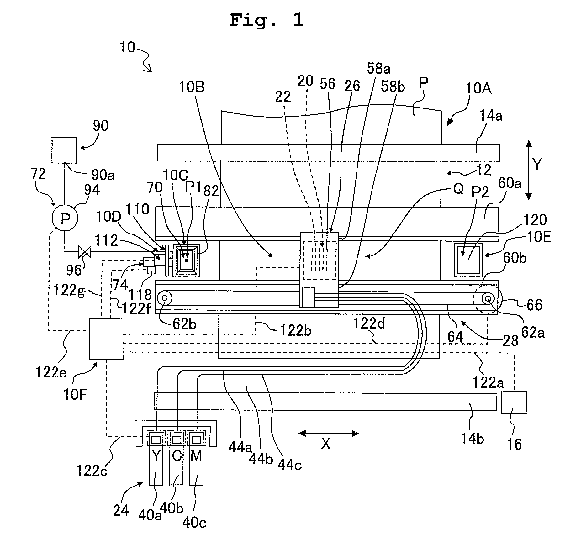
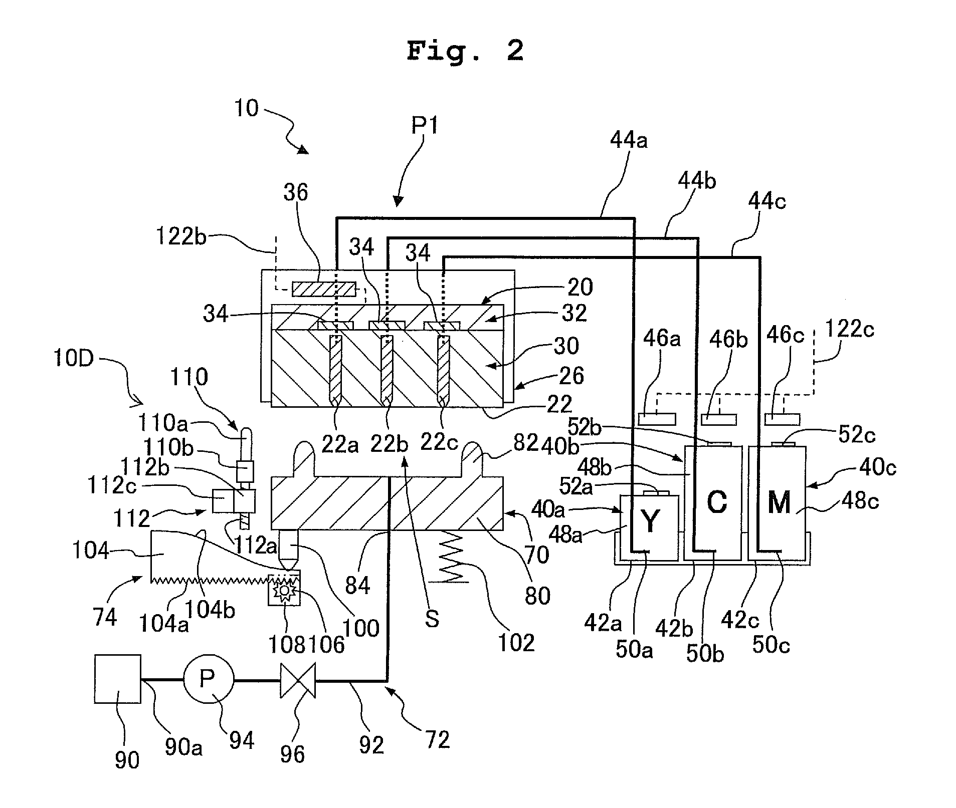
[0026]As shown in FIG. 1, an ink jetting apparatus 10 according to a first embodiment includes: a paper transporting unit 10A transporting a paper P as a “jetting target” to a printing zone Q; a printing unit 10B printing an image to the paper P transported to the printing zone Q; a purge unit 10C performing a “purge operation”; a wiping unit 10D performing a “wiping operation”, a flushing unit 10E performing a “color mixture preventive flushing operation” as a “first flushing operation”; and a control unit 10F controlling these parts. Hereinafter, their structures will be concretely explained.

[0027]As shown in FIG. 1, the paper transport unit 10A includes: a transport route 12 guiding the paper P to the printing area Q; an upstream transport roller 14a disposed at a position, in the transport route 12, on an upstream of the printing zone Q; a downstream transport roller 14b disposed at a position, in the transport route 12, on a downstream of the printing area Q; and a driving moto...


PUM


Abstract

There is provided a liquid jetting apparatus including: a first and a second cartridge attaching section; a liquid jetting head on which a plurality of first nozzles and a plurality of second nozzles are formed and which has a plurality of driving sections provided corresponding to the nozzles respectively; and a flushing control unit which operates the driving sections to cause execution of a first flushing operation in which an amount of the liquid forcibly jetted from the first nozzles is made smaller than an amount of the liquid forcibly jetted from the second nozzles when a height of the first cartridge is greater than a height of the second cartridge.

Description

CROSS REFERENCE TO RELATED APPLICATION[0001]The present application claims priority from Japanese Patent Application No. 2009-200947, filed on Aug. 31, 2009, the disclosure of which is incorporated herein by reference in its entirety.BACKGROUND OF THE INVENTION[0002]1. Field of the Invention[0003]The present invention relates to a liquid jetting apparatus forcibly discharging a liquid which has flowed back into a liquid jetting head.[0004]2. Description of the Related Art[0005]As an example of a conventional liquid jetting apparatus, an ink jetting apparatus such as an ink-jet printer is known. A common ink jetting apparatus includes an ink-jet head having a plurality of nozzles jetting inks and a plurality of driving parts corresponding to the nozzles, and at the time of printing, in response to the selective operation of each of the driving parts, the ink is jetted from a corresponding one of the nozzles toward a paper. Further, at the time of maintenance, after a nozzle cap is pl...

Claims


Application Information

Patent Timeline
Patent Type & Authority Patents(United States)
IPC IPC(8): B41J2/165
CPCB41J2/16526
Inventor NISHIDA, KATSUNORI
Owner BROTHER KOGYO KK
Learn More