Viscous coolant heater with variable coolant pump drive

a coolant heater and viscous technology, applied in the direction of circumferential flow pumps, fluid friction heating, gaseous engine fuels, etc., can solve the problems that the diesel engine has the additional challenge of providing sufficient heat and the engine may not naturally reject sufficient heat to the cooling system

Inactive Publication Date: 2013-06-18
BORGWARNER INC
View PDF27 Cites 11 Cited by
  • Summary
  • Abstract
  • Description
  • Claims
  • Application Information

AI Technical Summary

Problems solved by technology

Additionally, diesel engines have the additional challenge of providing sufficient heat when the vehicle is stuck in a traffic jam in cold ambient conditions.
Under some conditions, the engine may not naturally reject sufficient heat to the cooling system to maintain the engine to its set-point.

Method used


Image

  • Viscous coolant heater with variable coolant pump drive
  • Viscous coolant heater with variable coolant pump drive
  • Viscous coolant heater with variable coolant pump drive

Examples


Embodiment Construction

[0014]Supplementary coolant heaters for vehicles with diesel engines are typically in the range of 2 to 4 KW for peak power and are required to attain rapid heater / defroster performance after a cold start in cold (winter) ambient conditions. For some diesel engines, the continuation of supplemental heat is also required in extended idling conditions in cold ambient conditions.

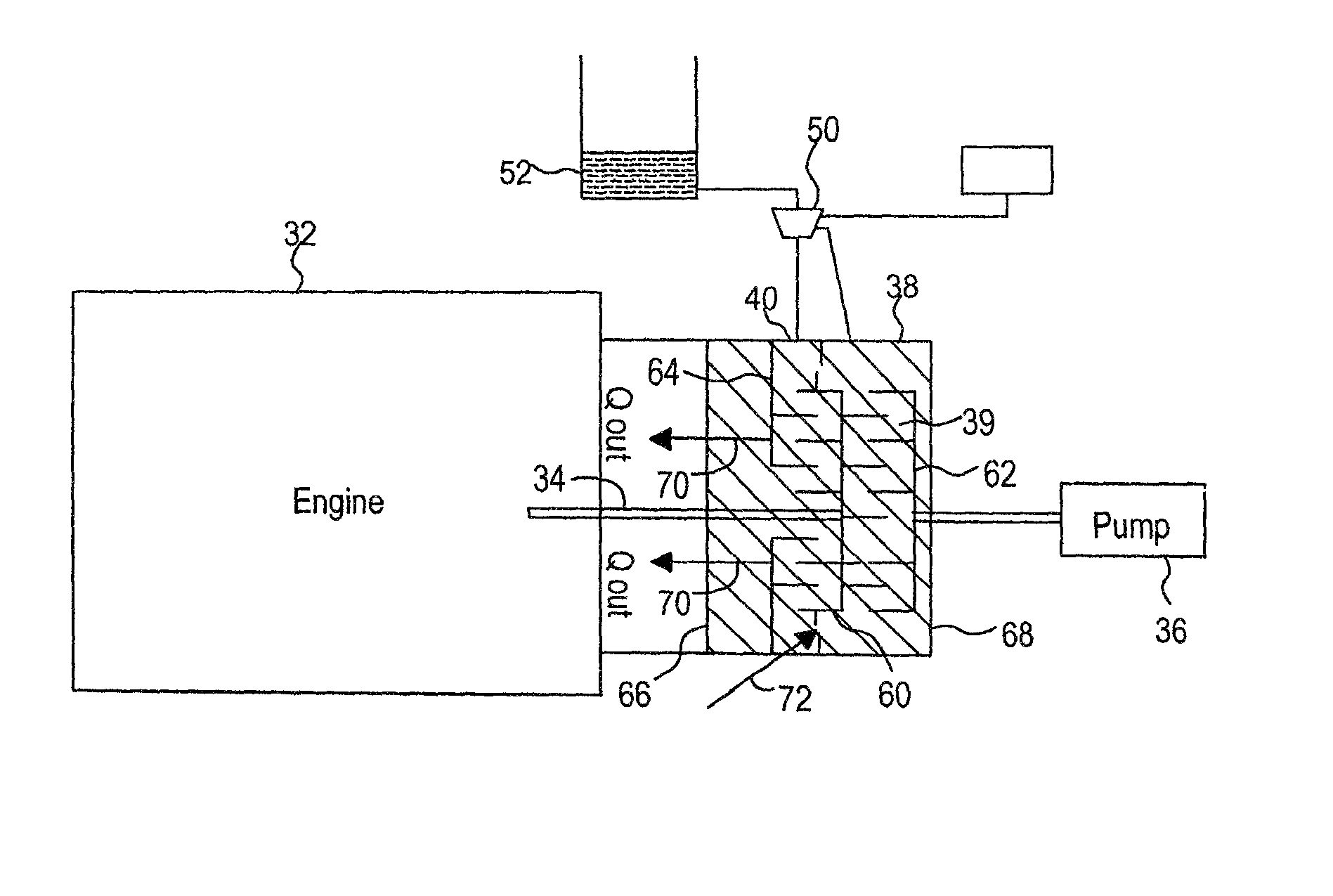
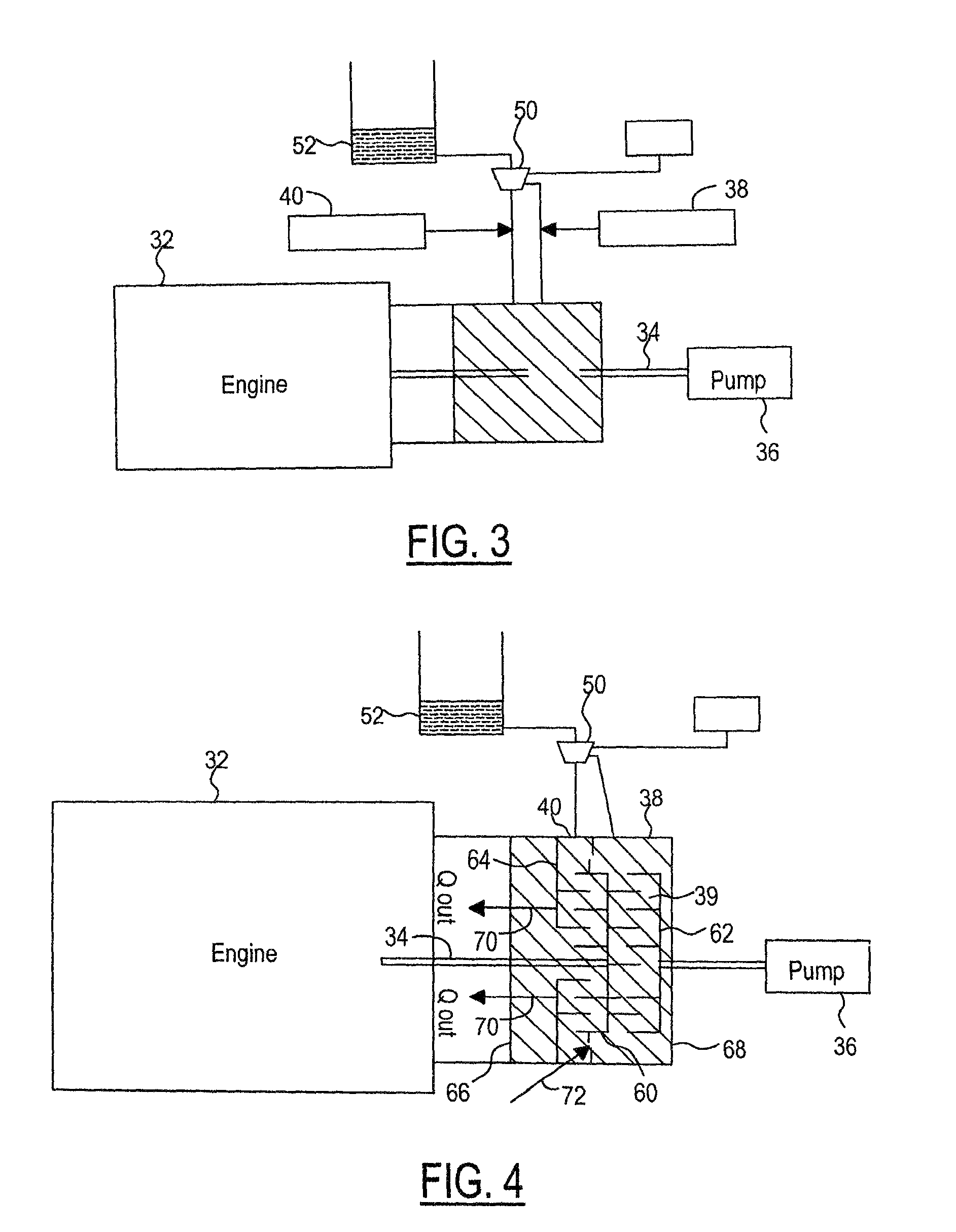
[0015]Coolant pumps for diesel engines are required to pump coolant in proportion to the power generated. The power dissipation requirement for a viscous heater (presumably at idle speed) and the total power transmission load (at peak engine speed) for a viscous pump drive in a vehicle are approximately the same.

[0016]For the initial warm-up phase of a diesel engine, the viscous heater must be filled and slipping and the viscous pump clutch must be operating somewhere between the low and high slip conditions. The colder the coolant, the slower the pump may be allowed to spin.

[0017]One embodiment in accordance w...


PUM


Abstract

A system for supplying supplemental heat to a vehicle, particularly a vehicle with a diesel engine, A driven viscous plate with different viscous clutch faces on either side is provided between the engine and the coolant pump. One side clutches to the engine structure (ground) to generate heat, and the other side clutches to the coolant pump to vary the pump drive. The two sides are controlled by a valve operated by signals from the engine computer. The valve varies the supply of viscous fluid from a common reservoir independently to both sides of the driven viscous plate. The signal from the engine control unit is based on the instantaneous desired supplemental heat and coolant flow. In another embodiment, two separate viscous clutches are utilized and positioned on opposite sides of the coolant pump.

Description

TECHNICAL FIELD[0001]The present invention relates to supplemental heating systems for vehicles and more particularly to supplemental heating systems particularly for vehicles with diesel engines.BACKGROUND OF THE INVENTION[0002]There is a demand in vehicles with internal combustion engines for supplemental heat during the warm-up phase that immediately follows a cold-start in cold ambient (winter) conditions. This is particularly true in vehicles with diesel engines since they warm up more slowly than spark-ignition engines. One of the main benefits of rapid warm-up of an engine is improved heater and defroster performance. Also, warm engines run more efficiently and produce lower emissions levels than cold engines.[0003]Additionally, diesel engines have the additional challenge of providing sufficient heat when the vehicle is stuck in a traffic jam in cold ambient conditions. Under some conditions, the engine may not naturally reject sufficient heat to the cooling system to mainta...

Claims


Application Information

Patent Timeline
Patent Type & Authority Patents(United States)
IPC IPC(8): B60H1/22B60H1/03B60H1/04F24J3/00
CPCF16D48/06B60H1/038F01P2060/18F16D2500/10418F16D2500/10468F16D2500/1062F16D2500/3064F16D2500/30803F16D2500/3122F16D2500/504F16D2500/5041B60H1/00314B60H1/22B60H2001/146F24V40/00
Inventor ROTH, DAVID B.WEBER, OLAF E.
Owner BORGWARNER INC
Why Eureka
Try Eureka