Ion detector

a technology of detectors and ion beams, applied in the field of ion detectors, can solve the problems of reducing the detection reducing the conversion efficiency of negative ions into secondary electrons, and difficulty in performing both attraction of negative ions, so as to improve the s/n ratio of ion detectors, and improve the incidence efficiency of positive ions

Active Publication Date: 2013-06-18
HAMAMATSU PHOTONICS KK
View PDF13 Cites 2 Cited by
  • Summary
  • Abstract
  • Description
  • Claims
  • Application Information

AI Technical Summary

Benefits of technology

[0005]However, in the ion detector for which a positive ion conversion dynode and a negative ion conversion dynode are separately provided, it is technically difficult to perform both attraction of negative ions and emission of secondary electrons by the negative ion conversion dynode, and the conversion efficiency from negative ions into secondary electrons is also reduced, and thus the detection efficiency of negative ions may be lowered.
[0006]It is therefore an object of the present invention to provide an ion detector that can improve the detection efficiency of positive ions and negative ions.

Problems solved by technology

However, in the ion detector for which a positive ion conversion dynode and a negative ion conversion dynode are separately provided, it is technically difficult to perform both attraction of negative ions and emission of secondary electrons by the negative ion conversion dynode, and the conversion efficiency from negative ions into secondary electrons is also reduced, and thus the detection efficiency of negative ions may be lowered.

Method used


Image

  • Ion detector
  • Ion detector
  • Ion detector

Examples


first embodiment

[First Embodiment]

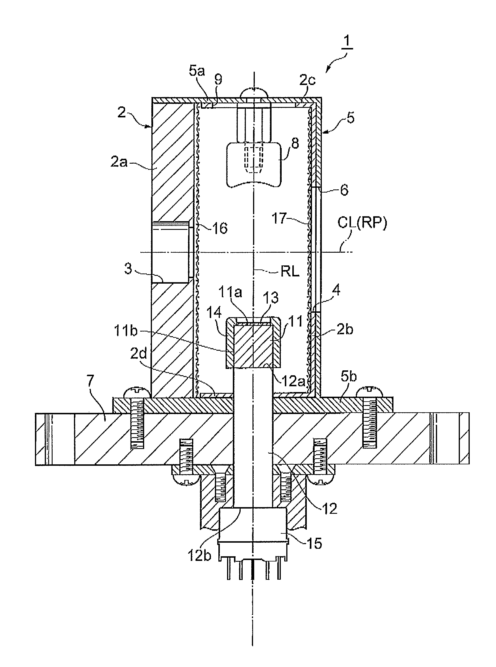
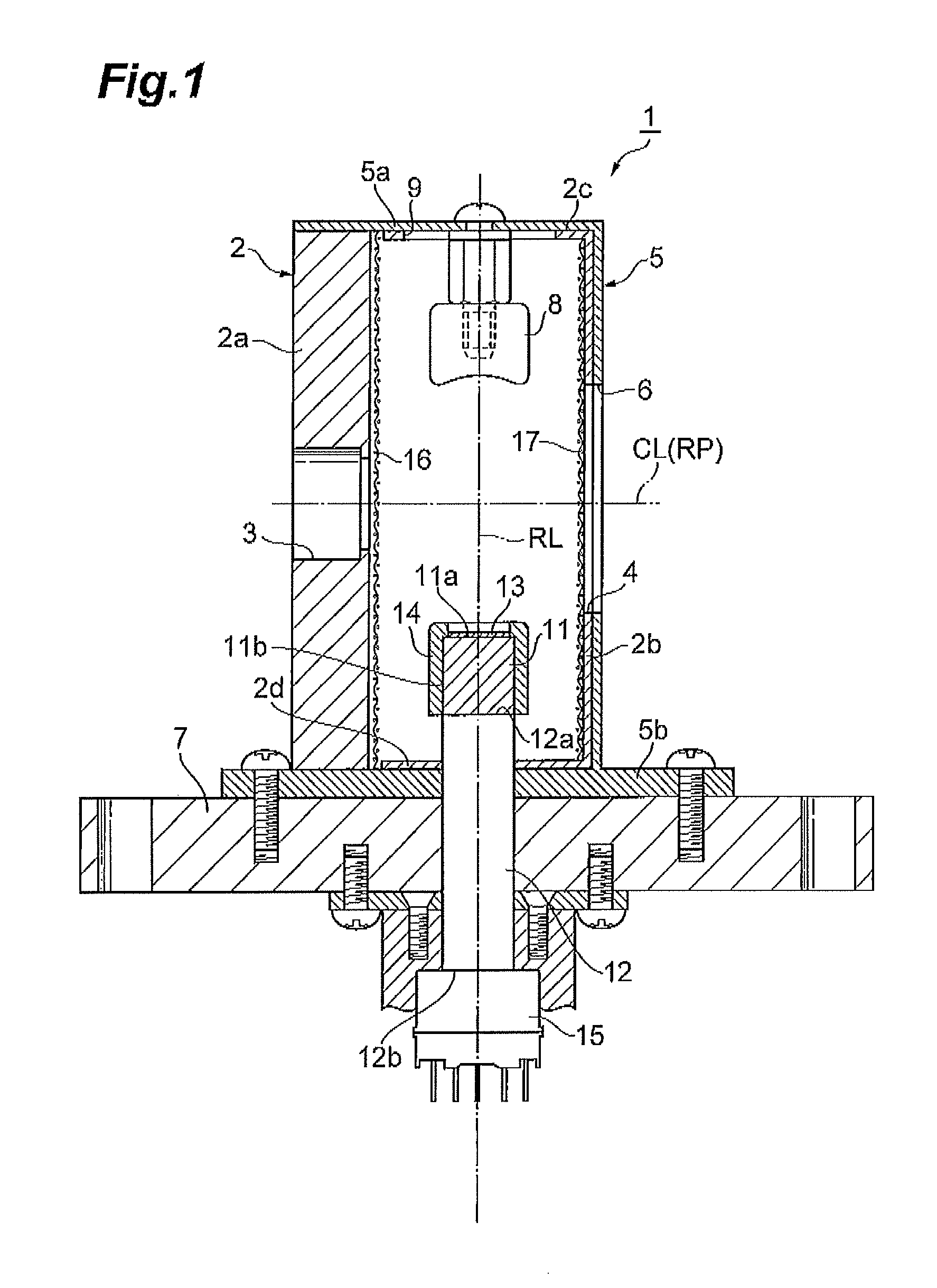
[0032]As shown in FIG. 1, an ion detector 1 includes a rectangular parallelepiped box-shaped chamber (housing) 2 made of SUS (stainless steel). In a side wall 2a of the chamber 2, an ion entrance 3 having a circular shape in section to let positive ions and negative ions enter are provided. In a side wall 2b of the chamber 2 opposed to the side wall 2a, an opening 4 opposed to the ion entrance 3 is provided. An outer surface of the chamber 2 excluding the side wall 2a is covered with an insulating member 5 made of a PEEK (polyether ether ketone) resin. In the insulating member 5, an opening 6 is provided so as to overlap with the opening 4 of the chamber 2. A bottom wall 5b of the insulating member 5 is formed like an outward flange. To the bottom wall 5b, a mounting plate 7 to mount the ion detector 1 at a predetermined position in, for example, a device (in a mass spectrometer or the like) that is vacuumed is fixed by a screw or the like.

[0033]In the chamber 2, a...

second embodiment

[Second Embodiment]

[0061]As shown in FIG. 8 and FIG. 9, an ion detector 10 is different from the foregoing ion detector 1 mainly in that a pair of electrode members 18 for converging trajectories of positive ions and negative ions that enter into the chamber 2 via the ion entrance 3 are disposed in the chamber 2.

[0062]The pair of electrode members 18 are located downstream of the mesh 16 and upstream of the dynode 8 and the conductive layer 13 (here, immediately behind the mesh 16) in the traveling direction of positive ions and negative ions that enter into the chamber 2 via the ion entrance 3. That is, the pair of electrode members 18 are located closer to the ion entrance 3 side than the dynode 8 and the conductive layer 13. Further, the pair of electrode members 18, when viewed from the ion entrance 3 side, face each other across the ion entrance 3 in a direction substantially perpendicular to the direction in which the dynode 8 and the conductive layer 13 are opposed (that is, ...

third embodiment

[Third Embodiment]

[0070]As shown in FIG. 12, an ion detector 20 is different from the foregoing ion detector 1 mainly in that a mesh (second mesh) 19 is placed at the ion entrance 3.

[0071]The mesh 19 is made of SUS, and is woven outside of the ion entrance 3 so as to extend along an outer surface of the side wall 2a of the chamber 2. That is, the mesh 19 is located at an outer side than the mesh 16. To the mesh 19, a positive potential and a negative potential are selectively applied so as to have an absolute value smaller than that of a potential to be applied to the mesh 16 and so as to have a polarity opposite to that of a potential to be applied to the mesh 16. For example, positive ions are detected, a negative potential of −300V is applied to the inner mesh 16, and a positive potential of +20V is applied to the outer mesh 19. On the other hand, when negative ions are detected, a positive potential of +300V is applied to the inner mesh 16, and a negative potential of −20V is ap...


PUM


Abstract

An ion detector for detecting positive ions and negative ions, includes a housing provided with an ion entrance to make the positive ions and the negative ions enter, a conversion dynode which is disposed in the housing and to which a negative potential is applied, a scintillator which is disposed in the housing and has an electron incident surface which is opposed to the conversion dynode and into which secondary electrons emitted from the conversion dynode are made incident, a conductive layer which is formed on the electron incident surface and to which a positive potential is applied, and a photodetector which detects light emitted by the scintillator in response to incidence of the secondary electrons.

Description

BACKGROUND OF THE INVENTION[0001]1. Field of the Invention[0002]The present invention relates to an ion detector for detecting positive ions and negative ions.[0003]2. Related Background Art[0004]Conventional ion detectors including conversion dynodes that emit secondary electrons by ion collisions, scintillators that emit light upon incidence of the secondary electrons emitted from the conversion dynodes, photodetectors that detect the light emitted by the scintillators have been known (refer to, for example, Japanese Patent Application Laid-Open No. H07-326315, French Patent Application Laid-Open No. 2658361 (FR2658361A1)). Here, a positive ion conversion dynode to which a negative potential is applied and a negative ion conversion dynode to which a positive potential is applied are separately provided for detection of positive ions and negative ions in some cases (refer to, for example, Japanese Patent Application Laid-Open No, H07-326315).SUMMARY OF THE INVENTION[0005]However, i...

Claims


Application Information

Patent Timeline
Patent Type & Authority Patents(United States)
IPC IPC(8): H01J49/02H01J43/10
CPCG01T1/185G01T1/2006G01T1/28
Inventor KOTANI, MASAHIROOHMURA, TAKAYUKISUYAMA, MOTOHIROKOBAYASHI, HIROSHI
Owner HAMAMATSU PHOTONICS KK
Why Eureka
Try Eureka