System and method for utility pole distributed solar power generation

a distributed solar and power generation technology, applied in the field of solar power generation, can solve the problems of large distance transmission loss, low cost of installation of such systems, and inability to minimize power loss during transmission

Inactive Publication Date: 2013-06-18
PETRASOLAR
View PDF11 Cites 13 Cited by
  • Summary
  • Abstract
  • Description
  • Claims
  • Application Information

AI Technical Summary

Benefits of technology

[0087]Various embodiments of the present invention provide the following one or more advantages. The distributed solar power generation system can be located close to the sites of power requirements. Further, as the AC electrical energy is generated at the utility pole, the utility grid 324 can be closer to the distributed solar power generation system as compared to the traditional power generation systems. Therefore, there is minimum distribution loss of electrical energy. Further, peak loading of the utility grid 324 can be matched in a more distributed fashion than with existing systems. The distributed solar power generation system requires a short lead time to provide power as it requires a lesser number of power lines, and the existing infrastructure such as bus-stands, electricity pole etc. can be used to set up the system. The distributed solar power generation system is also more reliable than traditional power generation systems. This is because in case of a fault in one of the utility poles, the shortcoming will be limited to that utility pole and can be supported by other utility poles of the distributed solar power generation system.

Problems solved by technology

The distribution of power from centralized power generation systems results in loss of energy during transmission over large distances.
Further, use of large distributed solar power generation systems in open areas does not minimize the power loss during transmission of electricity.
However, the cost of installation of such systems is relatively high.
Furthermore, several service companies are involved in these installations, which contribute to increased cost.

Method used


Image

  • System and method for utility pole distributed solar power generation
  • System and method for utility pole distributed solar power generation
  • System and method for utility pole distributed solar power generation

Examples


Embodiment Construction

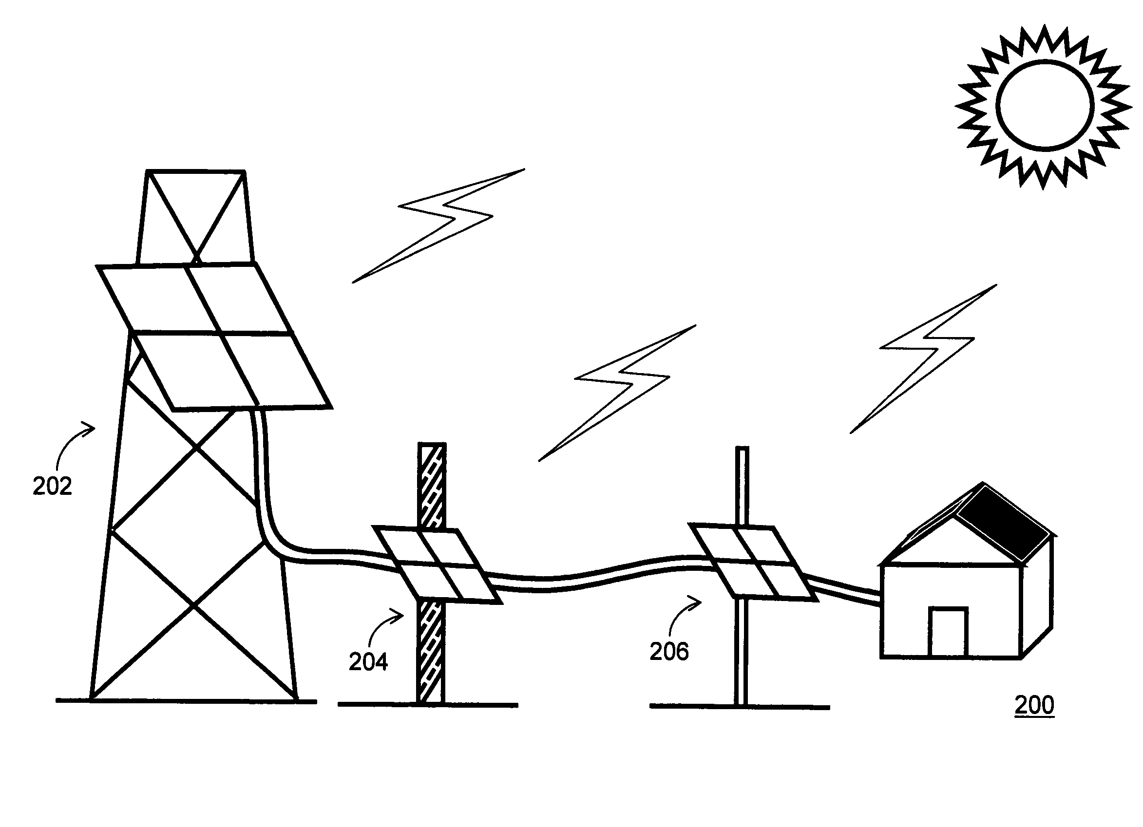
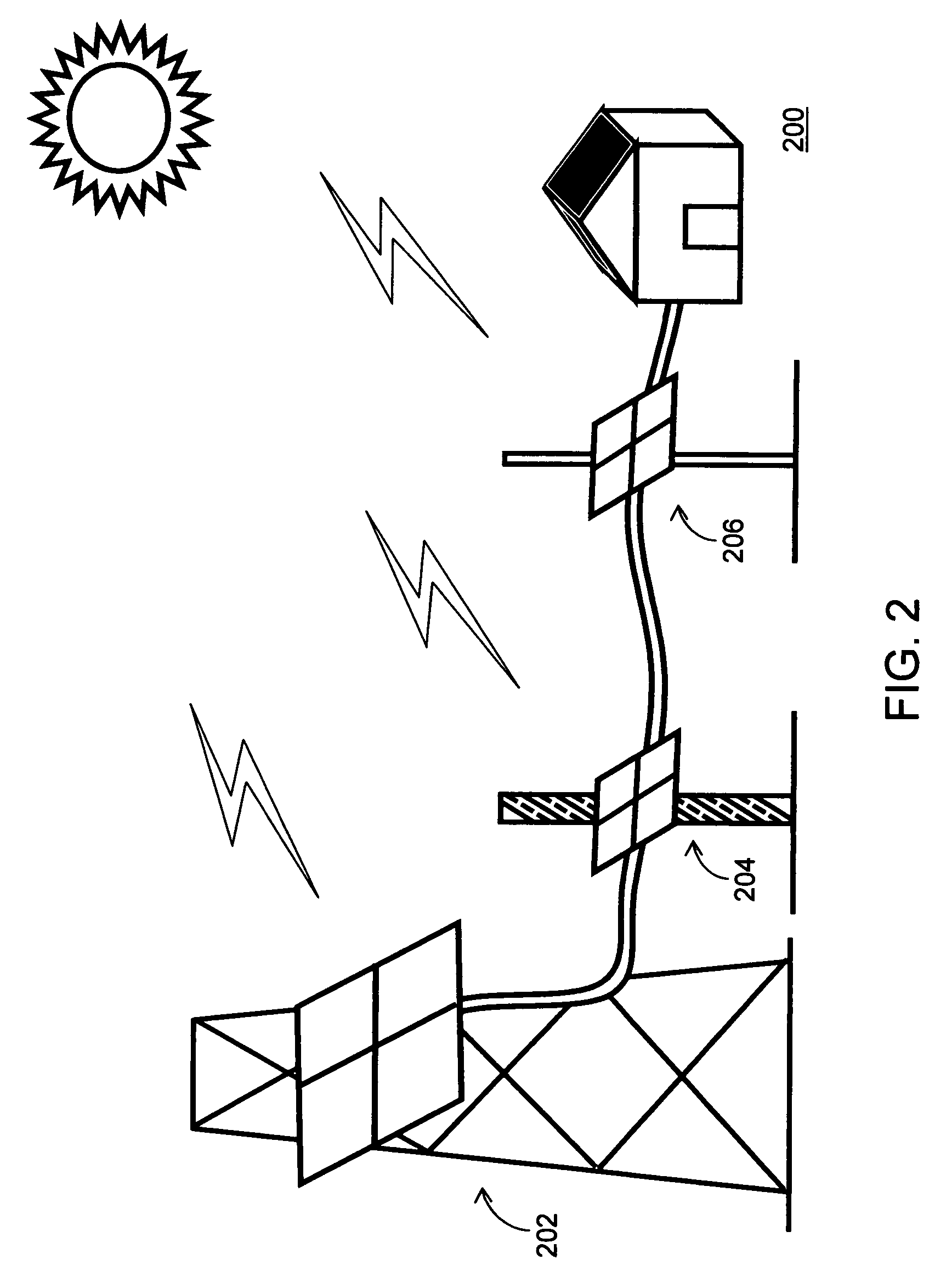
[0032]FIG. 2 illustrates an exemplary environment 200 for a decentralized distributed solar power generation system in which various embodiments of the present invention can be practiced. The decentralized distributed solar power generation system includes a distributed solar power generation system 202, a distributed solar power generation system 204 and a distributed solar power generation system 206. Each of the distributed solar power generation systems 202, 204, and 206, which are described in detail below, include one or more solar panels along with an inverter to convert solar energy to electrical energy. The one or more solar panels along with the inverter are mounted to a utility pole which can be a power pole, distribution pole, transmission pole, street light pole, traffic signal pole, a telephone pole, or any type of utility pole that is connected to the utility grid. Each of the distributed solar power generation systems 202, 204, 206 is a grid-tie system and can operat...


PUM


Abstract

A system and method for providing grid connected utility pole distributed solar power generation is disclosed. The system includes a utility pole, an inverter and one or more solar panels. Each of the one or more solar panels is mounted on the utility pole. The method includes receiving solar energy at the one or more solar panels. The one or more solar panels convert the solar energy to direct current (DC) electrical energy. Further, the method includes transmitting the DC electrical energy to the inverter, which is mounted on the utility pole. The inverter can be integrated with one or more solar panels to form an alternating current photovoltaic (AC PV) module. Furthermore, the method includes converting the DC electrical energy to alternating current (AC) electrical energy by the inverter and transmitting the AC electrical energy to a grid for power distribution.

Description

CROSS REFERENCE TO RELATED APPLICATION[0001]This application is a National Stage Application of International Application No. PCT / US08 / 12877 entitled “SYSTEM AND METHOD FOR UTILITY POLE DISTRIBUTED SOLAR POWER GENERATION” filed Nov. 18, 2008, which claims the benefit under provisions of 35 U.S.C. §119(e) of U.S. Provisional Application No. 61 / 137,679, filed Aug. 1, 2008, both of which are incorporated herein by reference in their entirety.BACKGROUND OF THE INVENTION[0002]The invention relates generally to solar power generation, and more particularly, to a system and method for utility pole distributed solar power generation.[0003]Power generation and distribution has been a backbone of rapid growth of modern times. Traditionally, large-scale power generation can be classified broadly as power generation from fossil fuel sources such as coal, oil, and natural gas, nuclear fuel sources, or renewable hydro / water sources. Utility power generation systems from these fuels have excellent...

Claims


Application Information

Patent Timeline
Patent Type & Authority Patents(United States)
IPC IPC(8): H02J1/00
CPCH02J3/38H02J3/01Y02E40/40
Inventor KURAN, SHIHAB
Owner PETRASOLAR
Why Eureka
Try Eureka