
OLED display with reduced power consumption

a technology of power consumption and oled display, which is applied in the direction of cathode-ray tube indicators, instruments, spectral modifiers, etc., can solve the problems of reducing the radiant efficiency to approximately 13 of the radiant efficiency, reducing and reducing the efficiency of the actual use so as to reduce the power consumption of the white oled display. , to achieve the effect of reducing th

Active Publication Date: 2013-06-18
GLOBAL OLED TECH
View PDF13 Cites 9 Cited by
  • Summary
  • Abstract
  • Description
  • Claims
  • Application Information

AI Technical Summary

Benefits of technology

[0014]According to a second aspect of the present invention, a method is provided for displaying an image on an OLED display with reduced power consumption, comprising:
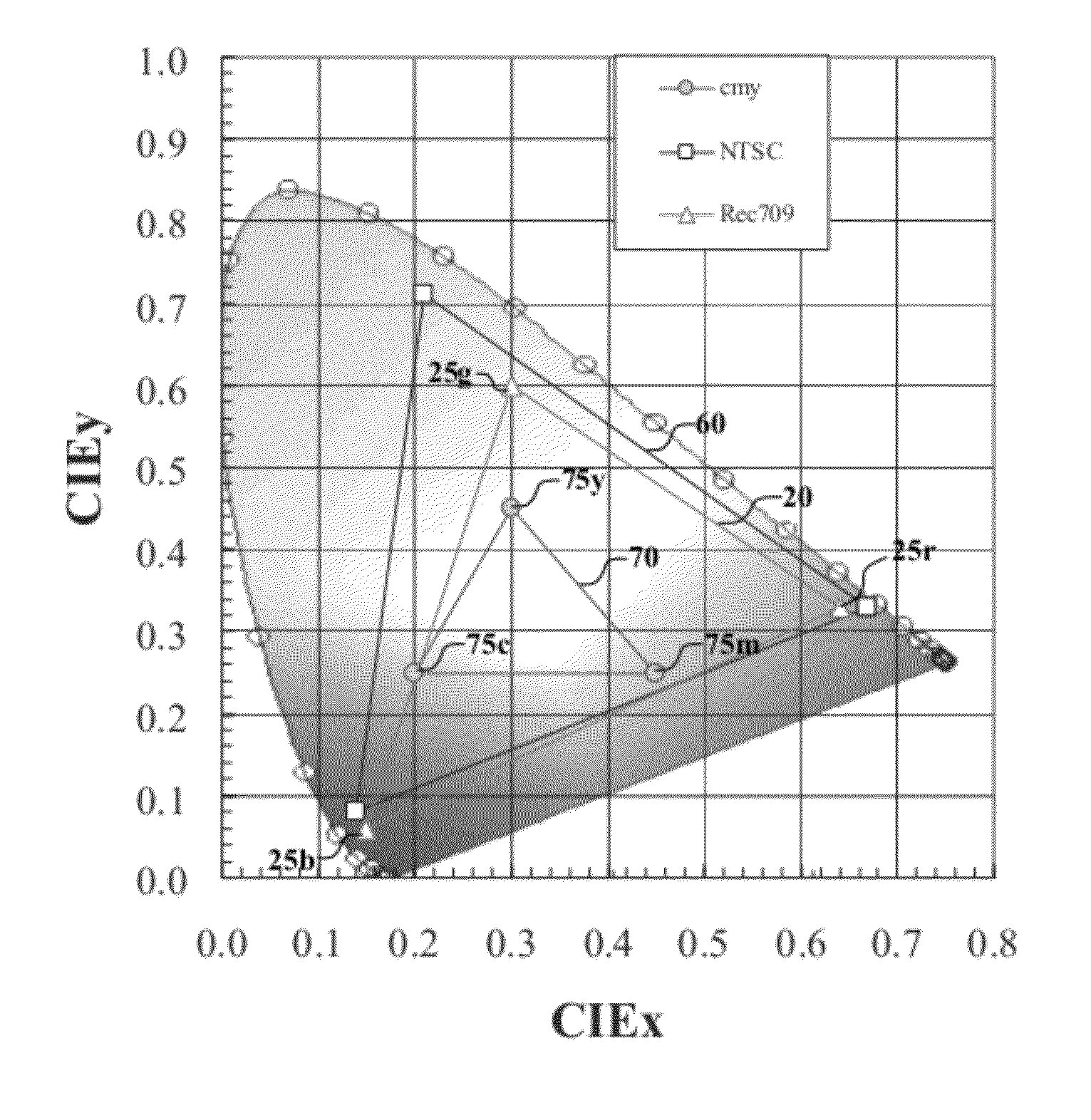
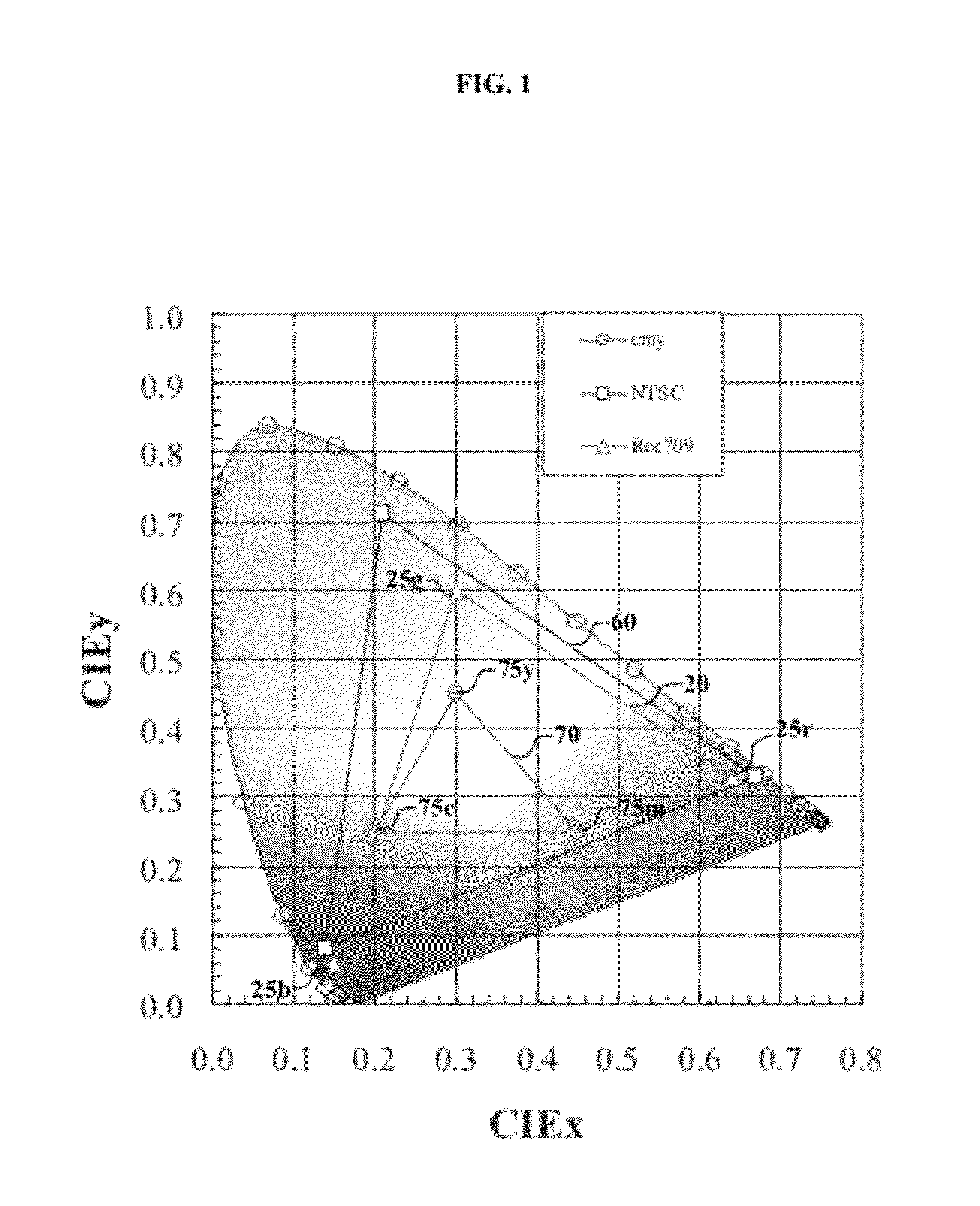
[0022]It is an advantage of the first aspect of this invention that a three-component input image signal can be converted to a five or more component drive signal to provide a display with a higher display white point luminance for the preponderance of images while maintaining color saturation for images having bright, highly saturated colors. It is an advantage of the second aspect of this invention that it can reduce the power consumption for a white OLED display, and can increase display lifetime. It is a further advantage of this invention that the reduced power consumption can reduce heat generation, and can eliminate the need for heat sinks presently required in some OLED displays of this type.

Problems solved by technology

However, in contrast to the manufacturing improvements achievable by white OLEDs in comparison to RGB OLEDs, white OLEDs suffer efficiency losses in actual use.
The use for color filters, therefore reduces the radiant efficiency to approximately ⅓ of the radiant efficiency of the white OLED.
Further, available color filters are often far from ideal, having peak transmissivity significantly less than 100%, with the green and blue color filters often having peak transmissivity below 80%.
Finally, to provide a display with a high color gamut, the color filters often need to be narrow bandpass filters and therefore they further reduce the radiant efficiency.
While these methods improve the efficiency of the resulting display, the improvement is often less than desired for many applications.

Method used


Image

  • OLED display with reduced power consumption
  • OLED display with reduced power consumption
  • OLED display with reduced power consumption

Examples


Embodiment Construction

[0037]The term “OLED device” is used in its art-recognized meaning of a display device comprising organic light-emitting diodes as pixels or subpixels. It can mean a device having a single pixel or subpixel. Each light-emitting unit includes at least a hole-transporting layer, a light-emitting layer, and an electron-transporting layer. Multiple light-emitting units can be separated by intermediate connectors. The term “OLED display” as used herein means an OLED device comprising a plurality of subpixels which can emit light of different colors. A color OLED device emits light of at least one color. The term “multicolor” is employed to describe a display panel that is capable of emitting light of a different hue in different areas. In particular, it is employed to describe a display panel that is capable of displaying images of different colors. These areas are not necessarily contiguous. The term “full color” is employed to describe multicolor display panels that are capable of emit...


PUM


Abstract

Methods for displaying an image on a color display having a target display white point luminance and chromaticity, and including three gamut-defining emitters defining a display gamut and two or more additional emitters which emit light within the display gamut; the method including receiving a three-component input image signal; transforming the three-component input image signal to a five-or-more component drive signal; and providing the drive signal to display an image corresponding to the input image signal. One method provides a reproduced luminance value higher than the sum of the respective luminance values of the three components of the input signal when reproduced with the gamut-defining emitters. Another method provides reduced power in an OLED display including a white-emitting layer with three color filters for gamut-defining emitters and two or more additional color filters for three additional within-gamut emitters.

Description

CROSS REFERENCE TO RELATED APPLICATIONS[0001]Reference is made to commonly assigned co-pending U.S. patent application Ser. No. 12 / 464,123, filed May 12, 2009 entitled “ELECTRO-LUMINESCENT DISPLAY WITH ADJUSTABLE WHITE POINT” by Miller et al., commonly assigned co-pending U.S. patent application Ser. No. 12 / 174,085, filed Jul. 16, 2008 entitled “CONVERTING THREE-COMPONENT TO FOUR-COMPONENT IMAGE” by Cok et al. and commonly assigned co-pending U.S. patent application Ser. No. 12 / 397,500, filed Mar. 4, 2009 entitled “FOUR-CHANNEL DISPLAY POWER REDUCTION WITH DESATURATION” by Miller et al; the disclosure of which is incorporated herein by reference.FIELD OF THE INVENTION[0002]The present invention relates to OLED devices, and in particular white OLED devices and a method for reducing the overall power requirements of the devices.BACKGROUND OF THE INVENTION[0003]An organic light-emitting diode device, also called an OLED, commonly includes an anode, a cathode, and an organic electrolumi...

Claims


Application Information

Patent Timeline
Patent Type & Authority Patents(United States)
IPC IPC(8): G09G3/32
CPCG09G3/2003G09G3/3208G09G3/3216G09G3/3225F21V9/08G09G3/3607G09G3/30G09G2300/0443G09G2300/0452G09G2320/0666G09G2330/021G09G2340/06
Inventor HAMER, JOHN W.MILLER, MICHAEL E.LUDWICKI, JOHN
Owner GLOBAL OLED TECH
Learn More