Stowable elevating trainable launcher (SETL)

a launcher and elevating technology, applied in the field of vertical launch systems, can solve the problems of unsuitability and inability to launch vertically

Inactive Publication Date: 2013-06-25
LOCKHEED MARTIN CORP
View PDF33 Cites 12 Cited by
  • Summary
  • Abstract
  • Description
  • Claims
  • Application Information

AI Technical Summary

Benefits of technology

[0008]The inventors of the present invention recognized that munitions that are unsuitable or sub-optimal for vertical launches were unavailable for use with vertical launching systems, thus foreclosing important defense, attack, and cost-savings opportunities for VLS-equipped ships (and other non-ship platforms). A VLS could be substantially more versatile if it accommodated munitions such as torpedoes, counter-measures, direct-fire munitions, point-and-shoot munitions, and a variety of other missiles and equipment. Likewise, an ALS could provide added flexibility if it could accommodate these types of munitions.
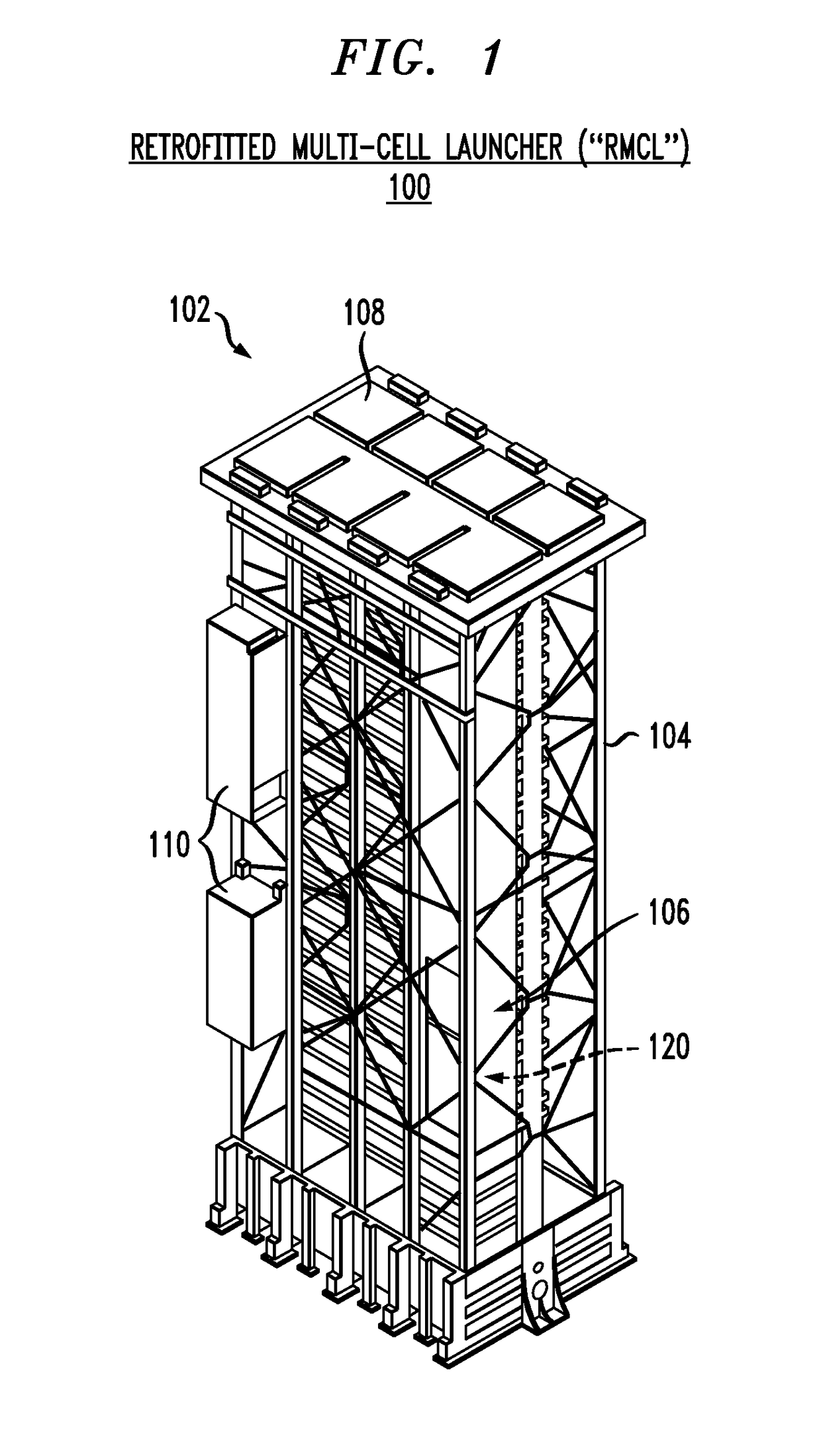
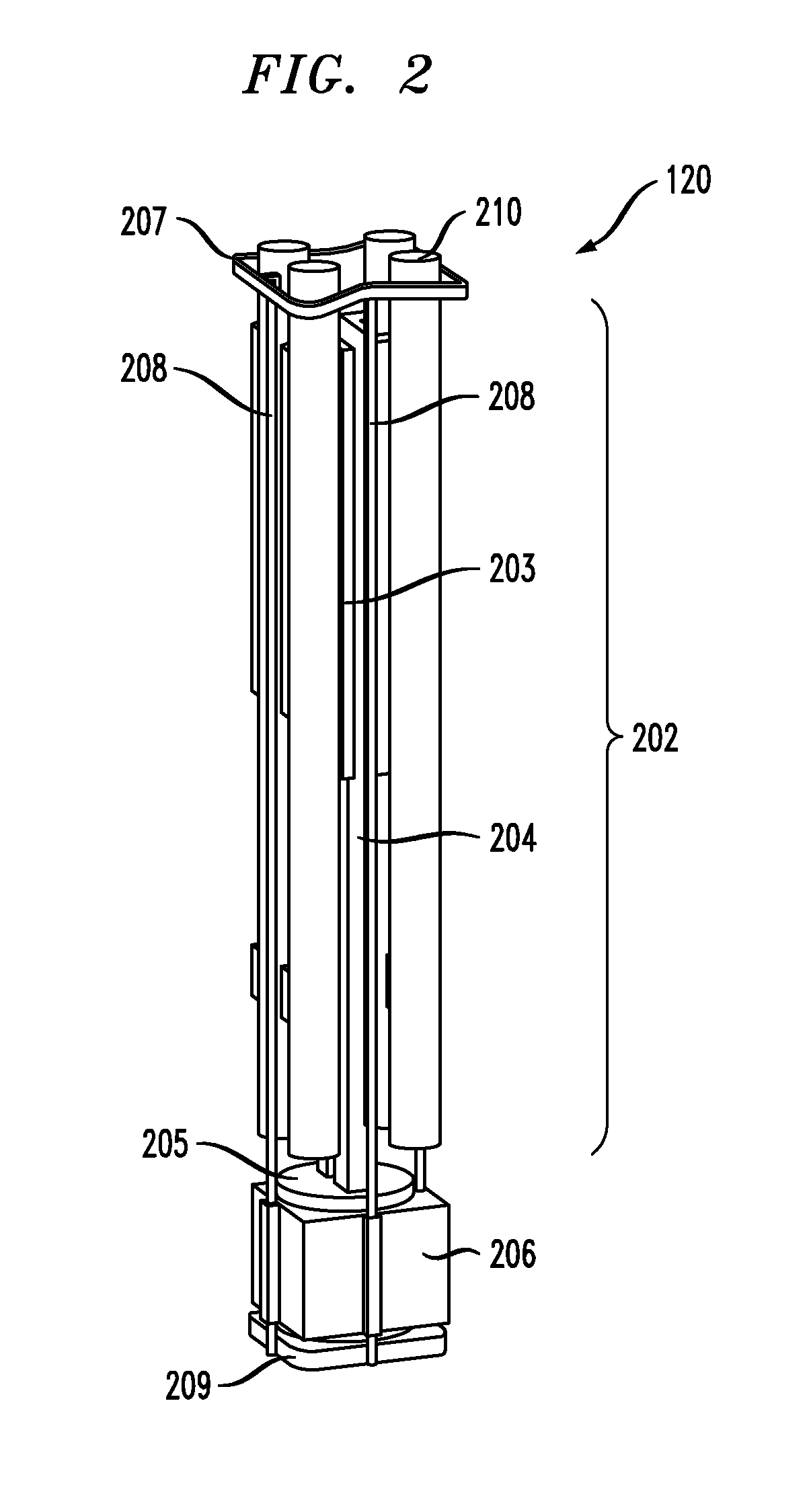
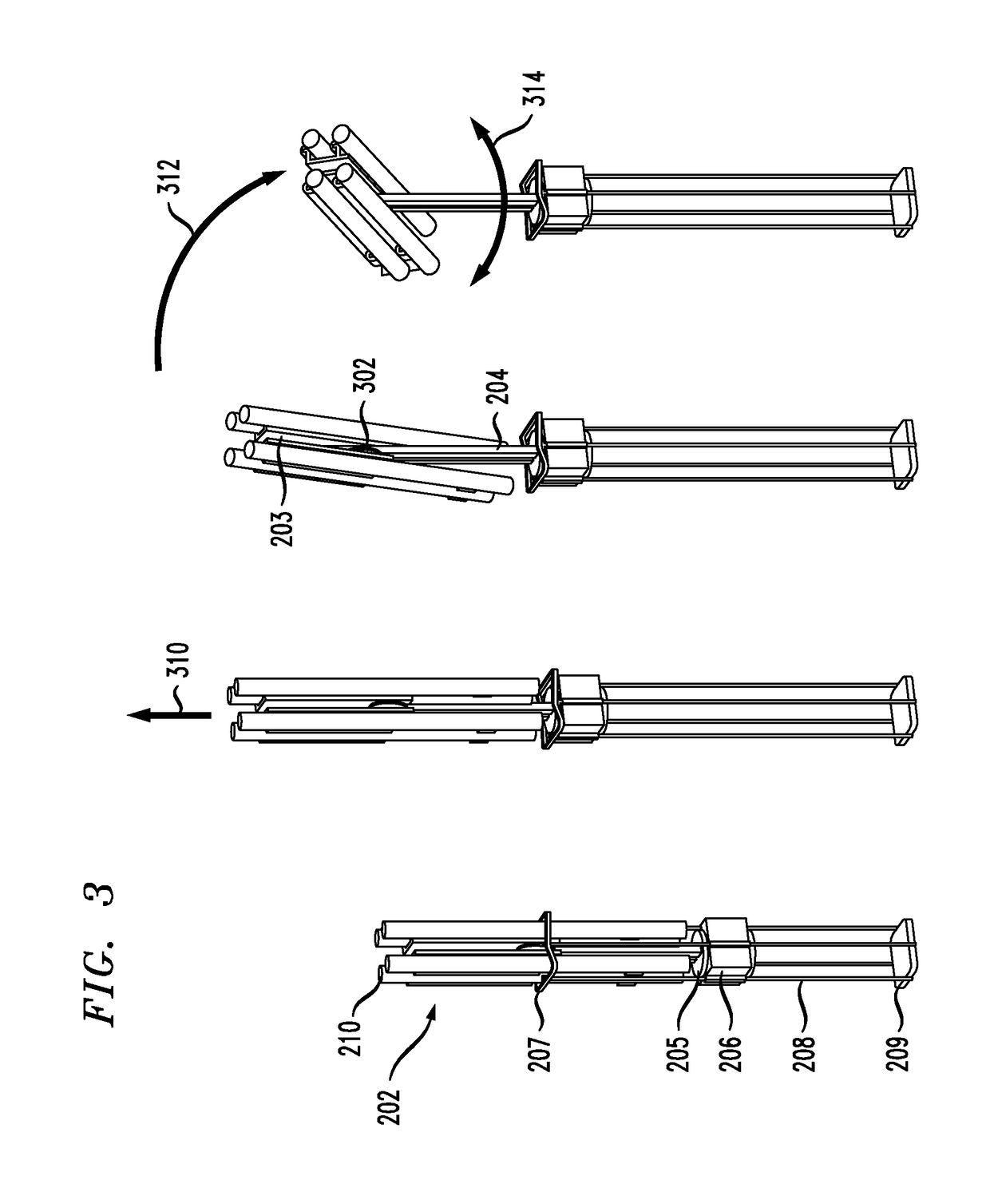
[0015]To launch a munition when the SETL is in a stowed state, the elevation drive lifts the munition frame structure above the top hatchway of the VLS cell. In some illustrative embodiments, this means that the elevation drive lifts the munition frame structure to an above-deck position. After pivoting and rotating the munition frame structure to the proper elevation and azimuth, one or more missiles can be fired. Once the missile(s) is fired, the munition frame structure pivots to align with the longitudinal axis of the upright support structure. This allows the munition frame structure to fit within the VLS cell. The elevation drive then lowers the munitions adapter into the interior of the VLS cell.
[0018]The SETL thus provides a launcher that allows munitions to be integrated into a VLS without the expense and effort of modifying the munition or the host launching system. In the illustrative embodiments where the SETL is used in conjunction with a MK 41 VLS, the savings and streamlining advantages are significant. Further, by tapping the ship's existing electrical power system, some embodiments of the SETL do not require added power sub-systems dedicated to the non-vertical-launch munitions.
[0021]Importantly, the SETL's stowed components are environmentally protected from harsh conditions outdoors or above-deck on a ship. The SETL components, including the munition frame structure and the elevation drive, as well as any munitions equipped in the SETL, are all protected and sealed within the VLS cell hosting the SETL. Optionally, these components can be subjected to additional special environmental conditions within the sealed VLS cell.

Problems solved by technology

As noted, non-vertical launch munitions are known in the art to be sub-optimal, and even unsuitable, for vertical launches.

Method used


Image

  • Stowable elevating trainable launcher (SETL)
  • Stowable elevating trainable launcher (SETL)
  • Stowable elevating trainable launcher (SETL)

Examples


Embodiment Construction

[0033]The following terms are defined for use in this disclosure and in the accompanying claims:[0034]“Operatively coupled” means that the operation of one element or device affects another device, wherein the devices need not be physically coupled. For example, a laser and a mirror are operatively coupled if a laser directs a beam of light to the mirror.[0035]“Physically connected” or “physically coupled” means in direct physical contact and affixed (e.g., a mirror that is mounted on a linear motor).[0036]“Vertical,” in the context of a launch, means a direction that is perpendicular to the plane of the deck of a ship.[0037]“Upward” or “Upwards” is used synonymously with “vertical” herein.[0038]“Non-vertical,” in the context of launch, means a horizontal or an acute-angle launch trajectory, such as might be associated with torpedoes, counter-measures, direct-fire munitions, point-and-shoot munitions, etc.[0039]“Non-vertical launch munition” means a munition that is generally known ...


PUM


Abstract

A system and method for launching non-vertical launch munitions with a non-vertical launch trajectory from a launcher that is operationally coupled to a vertical launching system (VLS). The inventors of the present invention recognized that munitions that are unsuitable for vertical launches were unavailable for use with vertical launching systems, thus foreclosing important defense, attack, and cost-savings opportunities for VLS-equipped platforms. A VLS could be substantially more versatile if it accommodated munitions such as torpedoes, counter-measures, direct-fire munitions, point-and-shoot munitions, and a variety of other missiles and equipment. The launcher according to the present invention is also stowable in an upward orientation within a cell of the host vertical launching system.

Description

CROSS REFERENCE TO RELATED APPLICATIONS[0001]The underlying concepts, but not necessarily the language, of the following case are incorporated by reference:[0002]U.S. patent application Ser. No. 12 / 274,409, filed 20 Nov. 2008, titled “Adaptable Launching System,” which published as U.S. Patent Application Publication No. 2009 / 0126556 A1 (attorney docket 711-239us).If there are any contradictions or inconsistencies in language between this application and one or more of the cases that are incorporated by reference, the claims in the present case are to be interpreted consistent with the language in the present case.FIELD OF THE INVENTION[0003]The present invention relates to launching munitions in general, and, more particularly, to launching from a vertical launching system.BACKGROUND OF THE INVENTION[0004]Modern warships use guided missiles as their principal offensive and defensive weapons. Since a naval engagement may be protracted, a warship must have many missiles available for...

Claims


Application Information

Patent Timeline
Patent Type & Authority Patents(United States)
IPC IPC(8): F41F3/04
CPCF41A23/20F41F3/042F41F3/073
Inventor SKURDAL, DANIEL A.SNEDIKER, JOHNKALMS, WILLIAM
Owner LOCKHEED MARTIN CORP
Why Eureka
Try Eureka