Pressure feedback shuttle valve

a shuttle valve and feedback technology, applied in the field of valves, can solve the problems of causing shock or water hammer in the system, affecting the functioning of the system, and the shuttle poppet may oscillate back and forth more than is necessary for proper system functioning, so as to reduce the impact of the poppet engaging, dampen the oscillation, and reduce the shock

Inactive Publication Date: 2013-06-25
PARKER INTANGIBLES LLC
View PDF16 Cites 22 Cited by
  • Summary
  • Abstract
  • Description
  • Claims
  • Application Information

AI Technical Summary

Benefits of technology

[0012]The cushioning cavity adjacent the lower pressure inlet port is connected to the higher pressure inlet port by a control or feedback passage. By supplying fluid pressure from the higher pressure inlet port continuously into the collapsing cushioning cavity adjacent the other inlet port, shifting of the valve member or poppet from the first at rest position to the second at rest position can be slowed. This reduces the shock as the poppet reaches its second at rest position to close the second inlet port. This structure also reduces the impact of the poppet engaging its seat and dampens oscillation. The valve member or poppet of the present invention includes a feedback passage within the poppet directly connecting the higher pressure inlet port to the cushioning cavity adjacent the lower pressure inlet port, in both directions of movement of the poppet, which provides pressure feedback features for helping to reduce shock during poppet or valve member closing of the second inlet port.

Problems solved by technology

Depending upon the pressure levels, the pressure level differentials, the rate of change of those differentials, the valve and pipe sizes and lengths, the elasticity or capacitance of the system, the resulting speed of movement of the shuttle poppet and other factors, these conditions may produce shock or water hammer in the system as is well known.
Also, if the pressure differential between the first and second inlet ports is relatively small and / or it changes in direction rapidly and / or frequently, the shuttle poppet may oscillate back and forth more than necessary for proper system functioning.

Method used


Image

  • Pressure feedback shuttle valve
  • Pressure feedback shuttle valve
  • Pressure feedback shuttle valve

Examples


Embodiment Construction

[0020]The principles, embodiments and operation of the present invention are shown in the accompanying drawings and described in detail herein. These drawings and this description are not to be construed as being limited to the particular illustrative forms of the invention disclosed. It will thus become apparent to those skilled in the art that various modifications of the embodiments herein can be made without departing from the spirit or scope of the invention.

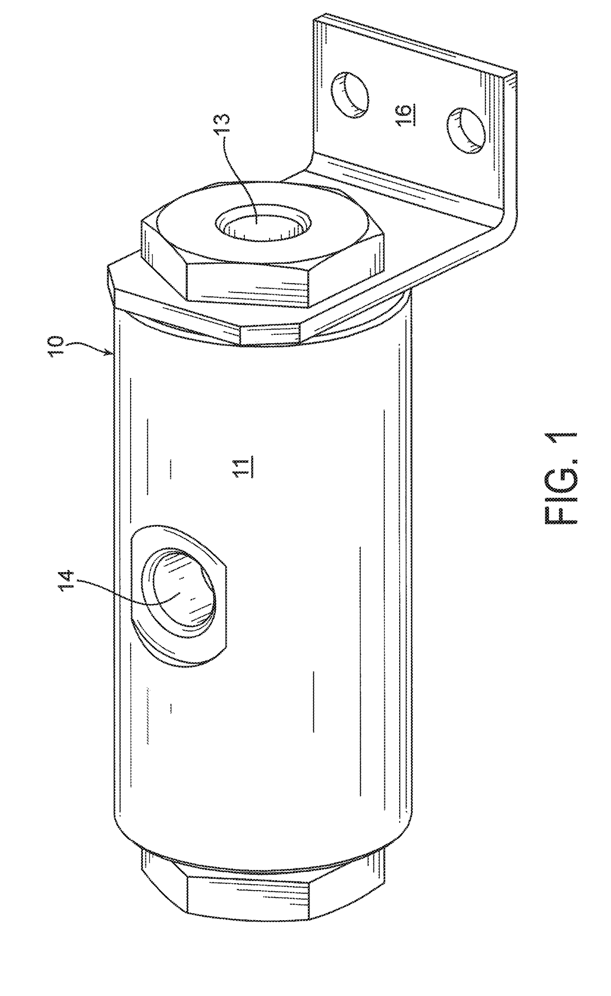
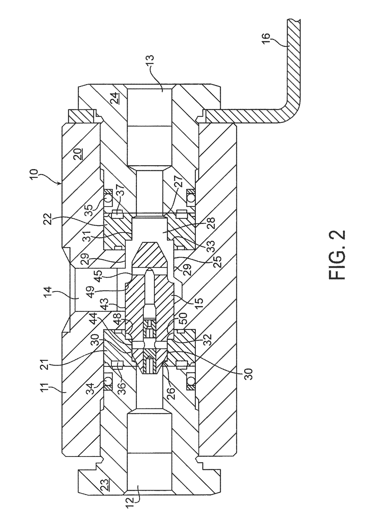
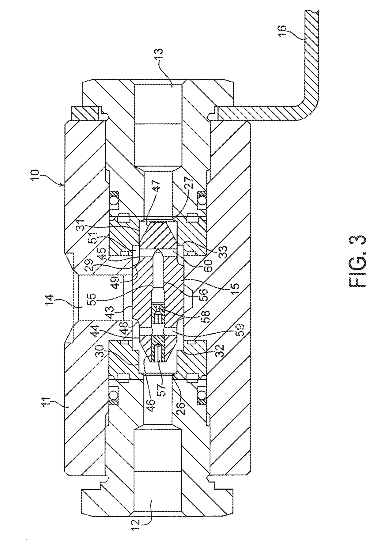
[0021]A preferred embodiment of a pressure feedback shuttle valve 10 according to the present invention is shown in FIGS. 1 through 5. Referring first to FIGS. 1 and 2, the shuttle valve 10 includes a valve body 11, a first inlet port 12, a second inlet port 13, an outlet port 14, and a shuttle poppet 15. A mounting bracket 16 is provided to secure the shuttle valve 10 to any suitable mounting structure.

[0022]The valve body 10 is of any suitable material, and is selected in a well known manner to accommodate the pressures, ...


PUM


Abstract

A shuttle valve 10 includes a valve body 11, a first inlet port 12, a second inlet port 13, an outlet port 14, and a shuttle poppet 15. The inlet ports 12 and 13 may be connected to different sources of fluid pressure, and the shuttle valve 10 connects the higher pressure one of the inlet ports 12, 13 to the outlet port 14 and isolates the lower pressure one of the inlet ports 12, 13 from the outlet port 14. First valve members 26, 46 selectively open and close fluid communication between the first inlet port 12 and the outlet port 14. Second valve members 27, 47 selectively open and close fluid communication between the second inlet port 13 and the outlet port 14. The shuttle valve 10 includes cushioning cavities 50 and 51 and feedback passages 56, 59 and 60 to reduce shock or water hammer in the system.

Description

CROSS REFERENCE TO RELATED APPLICATIONS[0001]The present application claims the benefit of the filing date of U.S. Provisional Patent Application Ser. No. 61 / 122,156, filed Dec. 12, 2008, the disclosure of which is incorporated herein by reference in its entirety.TECHNICAL FIELD[0002]This invention relates to a valve with a single outlet port and two fluid pressure inlet ports. The valve includes a shuttle poppet that connects the higher pressure one of the two inlet ports to the outlet port and isolates the lower pressure one of the two inlet ports from the outlet port. This type of valve is referred to as a shuttle valve.BACKGROUND OF THE INVENTION[0003]When a shuttle valve is used in a fluid system, the two inlet ports of the shuttle valve may be connected to different sources of fluid pressure. The different sources of fluid pressure may be at different pressure levels, and each of the pressure levels may increase or decrease with time. The shuttle poppet of the shuttle valve cl...

Claims


Application Information

Patent Timeline
Patent Type & Authority Patents(United States)
IPC IPC(8): G05D11/00
CPCF15B13/028Y10T137/7904Y10T137/2567Y10T137/2594
Inventor BRESNAHAN, KEVIN L
Owner PARKER INTANGIBLES LLC
Why Eureka
Try Eureka