
Integrated illumination apparatus and method of manufacturing same

a technology of integrated illumination and manufacturing methods, applied in the direction of discharge tube luminescnet screens, lighting support devices, door/window protective devices, etc., can solve the problems of affecting the quality of light, so as to prevent the wire from getting broken, reduce the localized concentration of pressure, and prevent the effect of deterioration

Active Publication Date: 2013-06-25
SHARP KK
View PDF2 Cites 11 Cited by
  • Summary
  • Abstract
  • Description
  • Claims
  • Application Information

AI Technical Summary

Benefits of technology

The solution effectively prevents wire deterioration and allows for the creation of large-area integrated illumination devices with reduced manufacturing costs by distributing stress and using small-sized organic electroluminescent elements.

Problems solved by technology

A vacuum process, which is one of methods for manufacturing the organic EL element, does not allow a large-sized organic EL element to be manufactured easily.
This is due to an enormous amount of takt time resulting from technical difficulty in manufacturing an organic EL element by use of a large-sized substrate in the vacuum process.
In addition, installing an apparatus for manufacturing the large-sized organic EL involves an enormous cost.

Method used


Image

  • Integrated illumination apparatus and method of manufacturing same
  • Integrated illumination apparatus and method of manufacturing same
  • Integrated illumination apparatus and method of manufacturing same

Examples


example 1

[0237]An organic EL illumination device employing an RGB-stacked white organic EL element that has a strip-like shape and is 450 mm long and 50 mm wide was manufactured. Specifically, a glass substrate about 1000 mm long, 70 mm wide, and 0.7 mm thick was used as each of the first substrate and the second substrate. A conductive wire 100 nm in thickness was formed on a surface of the first substrate under a water pressure of 6×10⁻⁴ Pa. Two organic EL elements were placed on the first substrate, and the conductive wire of the first substrate is connected with the organic EL elements. Subsequently, the first substrate and the second substrate were bonded with each other via resin, so that an illumination panel was manufactured.

[0238]Twenty-five illumination panels manufactured in this manner were placed on a ladder cord connecting the head box and the bottom rail, so that the illumination panels were connected with respective up-and-down cords extending from the head box. Specifically,...

example 2

[0241]An organic EL illumination device in which a connection point between an up-and-down cord and a branch wire was movable was manufactured. Except in this respect, the organic EL illumination device has the same configuration as that of the organic EL illumination device of Example 1.

[0242]In a similar manner with Example 1, the chromaticity and the color temperature of the obtained organic EL illumination device were measured. Similar results were obtained as those in Example 1, both with respect to chromaticity and color temperature.

example 3

[0243]An organic EL illumination device employing organic EL elements each of which has three areas of respective different colors (red, green, and blue) was manufactured. Except in this respect, the organic EL illumination device has the same configuration as that of Example 1. Voltages were applied to the conductive wires so that a ratio of light of luminescent colors red (R), green (G), and blue (B) emitted from the manufactured organic EL illumination device was 30%, 22% and 60%.

[0244]As in Example 1, the chromaticity and the color temperature of the obtained organic EL illumination device was measured. The measured chromaticity was (0.31, 0.33) and the measured color temperature was 6800 K. That is, the organic EL illumination device emitted daytime white-colored light.


PUM


Abstract

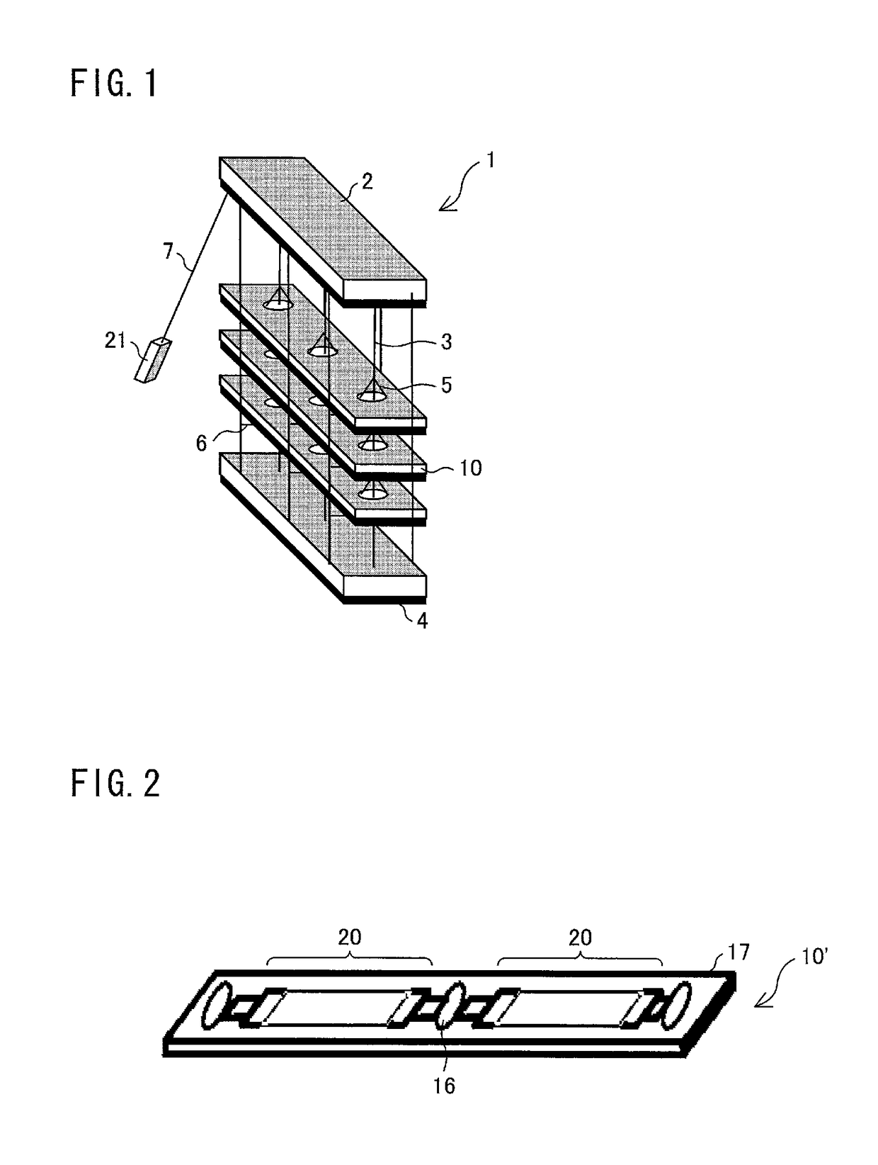
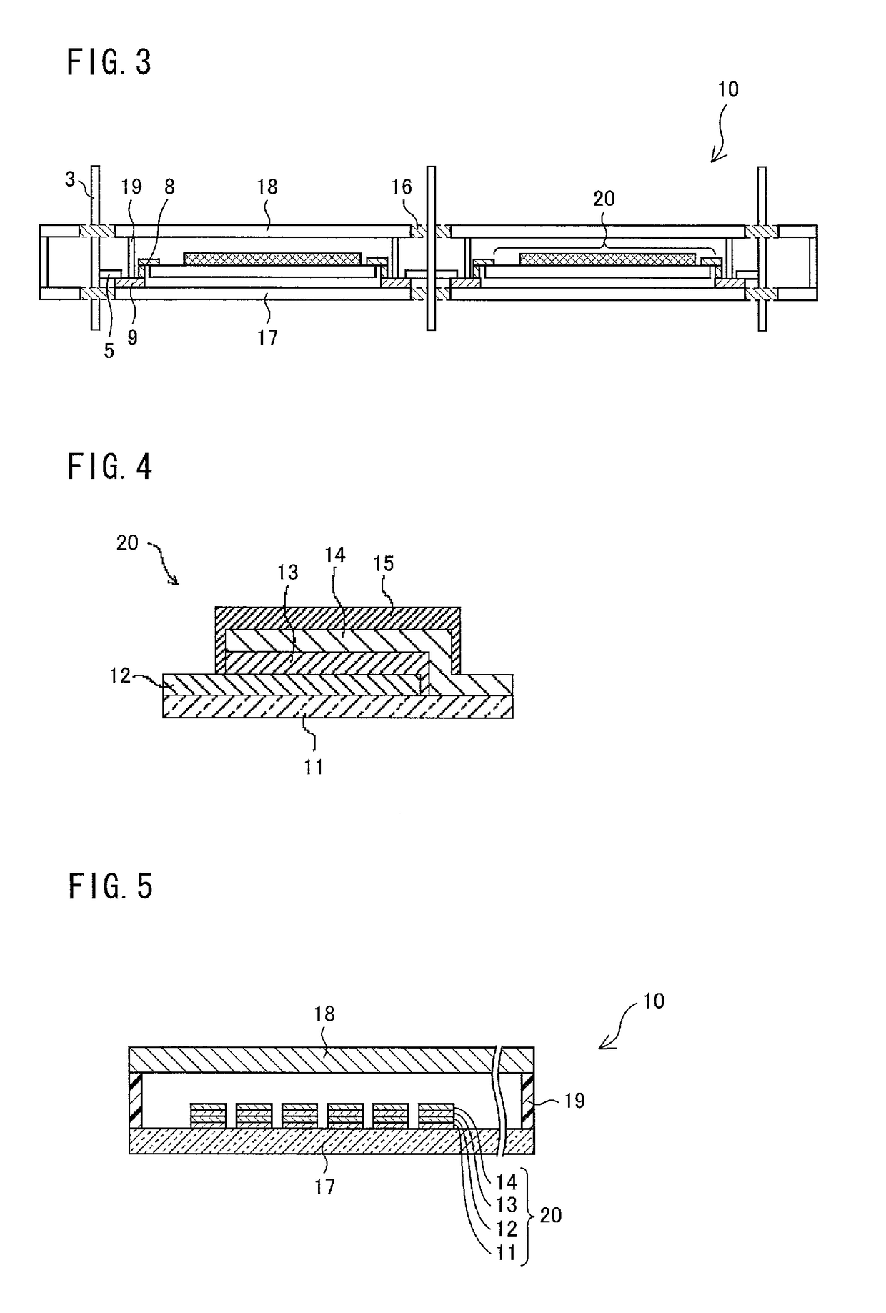
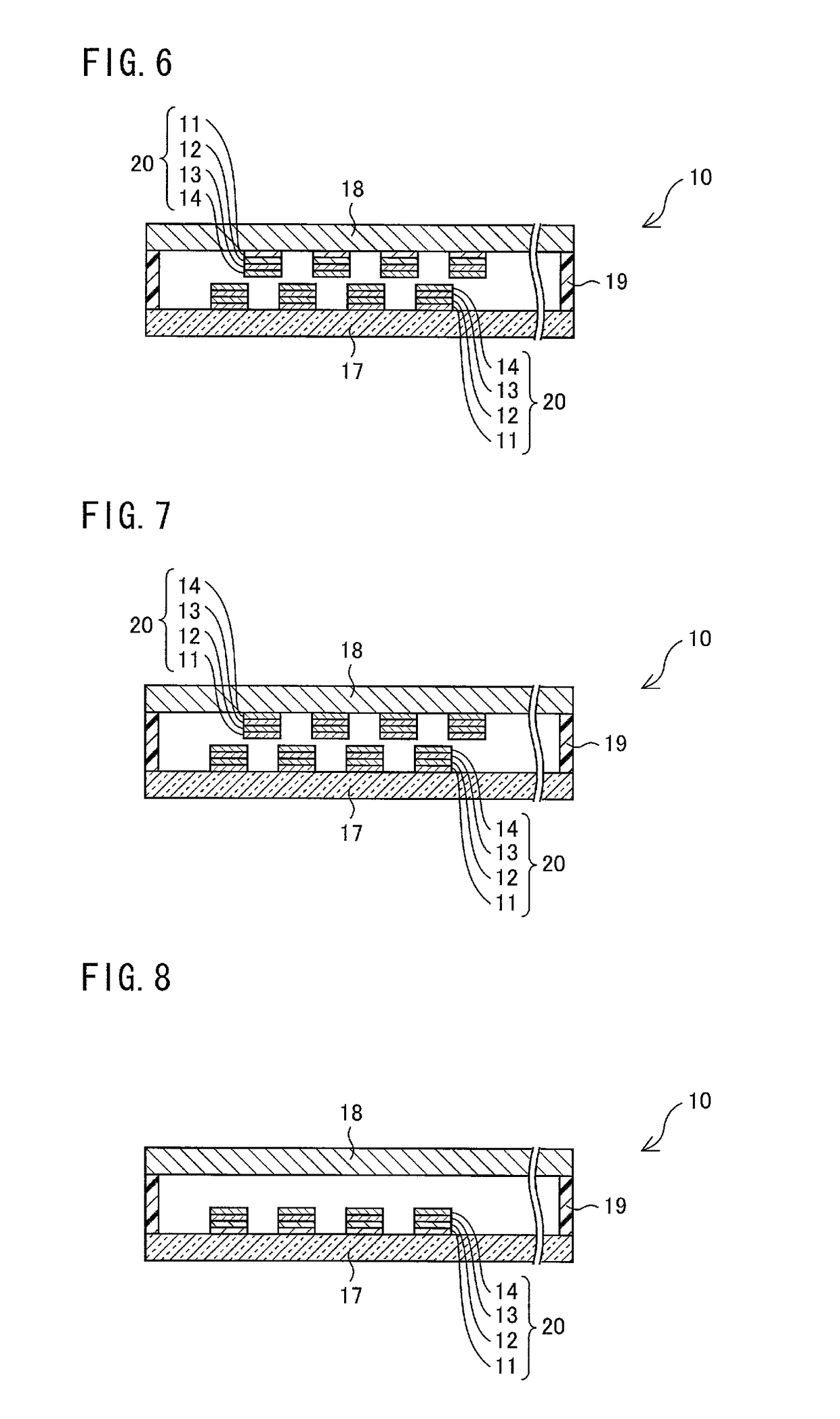
One or more illumination panels (10) are hung by up-and-down cords (3). The up-and-down cords (3) have a function of hanging the illumination panels (10) and a function of supplying electric power to the illumination panels (10). Pulling a rod (7), which is a take-up tool causes the up-and-down cords (3) to be taken up and, at the same time, the bottom rail (4) and the illumination panels (10) are also raised. At this time, the up-and-down cords (3) are taken up into the head box (2). As such, when the bottom rail (4) is raised, the up-and-down cords (3) are taken up without bending. This makes it possible to distribute stress that may otherwise be concentrated locally on the up-and-down cords (3). As a result, the up-and-down cords (3) can be prevented from getting broken due to deterioration caused by concentration of stress on the up-and-down cords (3), which concentration is caused by bending etc. of the up-and-down cords (3).

Description

CROSS REFERENCE TO RELATED APPLICATIONS[0001]This is a U.S. National Phase patent application of PCT / JP2011 / 053286, filed Feb. 16, 2011, which claims priority to Japanese Patent Application No. 2010-032404, filed Feb. 17, 2010, each of which is hereby incorporated by reference in the present disclosure in its entirety.TECHNICAL FIELD[0002]The present invention relates to an integrated illumination device including a cord functioning as wire, and a method for manufacturing the integrated illumination device.BACKGROUND ART[0003]In recent years, a light source device that employs an organic electroluminescent element (hereinafter referred to as organic EL element) is attracting attention as a type of flat light source devices. The light source device employing the organic EL element has excellent properties such as self-light emission, wide viewing angle, and high-speed response.[0004]The organic EL element generally includes an organic layer on a transparent substrate, which organic l...

Claims


Application Information

Patent Timeline
Patent Type & Authority Patents(United States)
IPC IPC(8): H01J1/62
CPCE06B9/303E06B9/384E06B9/386F21V21/16F21V21/38E06B2009/247F21V33/0016F21V33/006H01L2251/5361F21Y2105/008F21Y2105/00F21Y2115/15
Inventor YAMADA, MAKOTOFUJITA, YOSHIMASAKOBAYASHI, YUHKIOKAMOTOOGATA, HIDENORI
Owner SHARP KK
Learn More