
Local concentration management system

a concentration management system and concentration management technology, applied in the field of local concentration management system, can solve the problems of limited access to treatment sites, difficulty in site-specific drug delivery, and limited number of limitations, and achieve the effect of convenient handling, low volume, and extremely small volum

Inactive Publication Date: 2007-07-19
DURECT CORP
View PDF15 Cites 1 Cited by
  • Summary
  • Abstract
  • Description
  • Claims
  • Application Information

AI Technical Summary

Benefits of technology

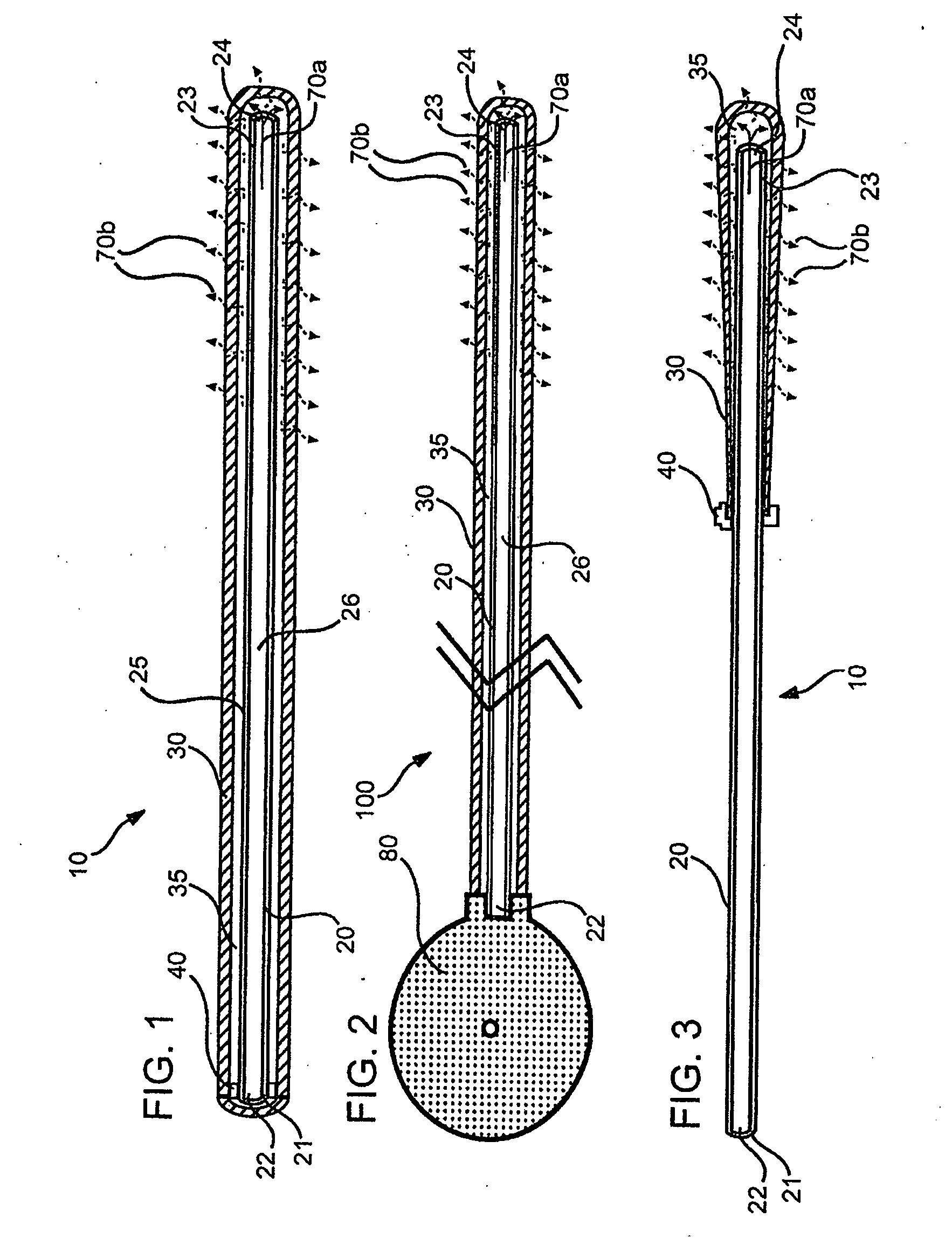
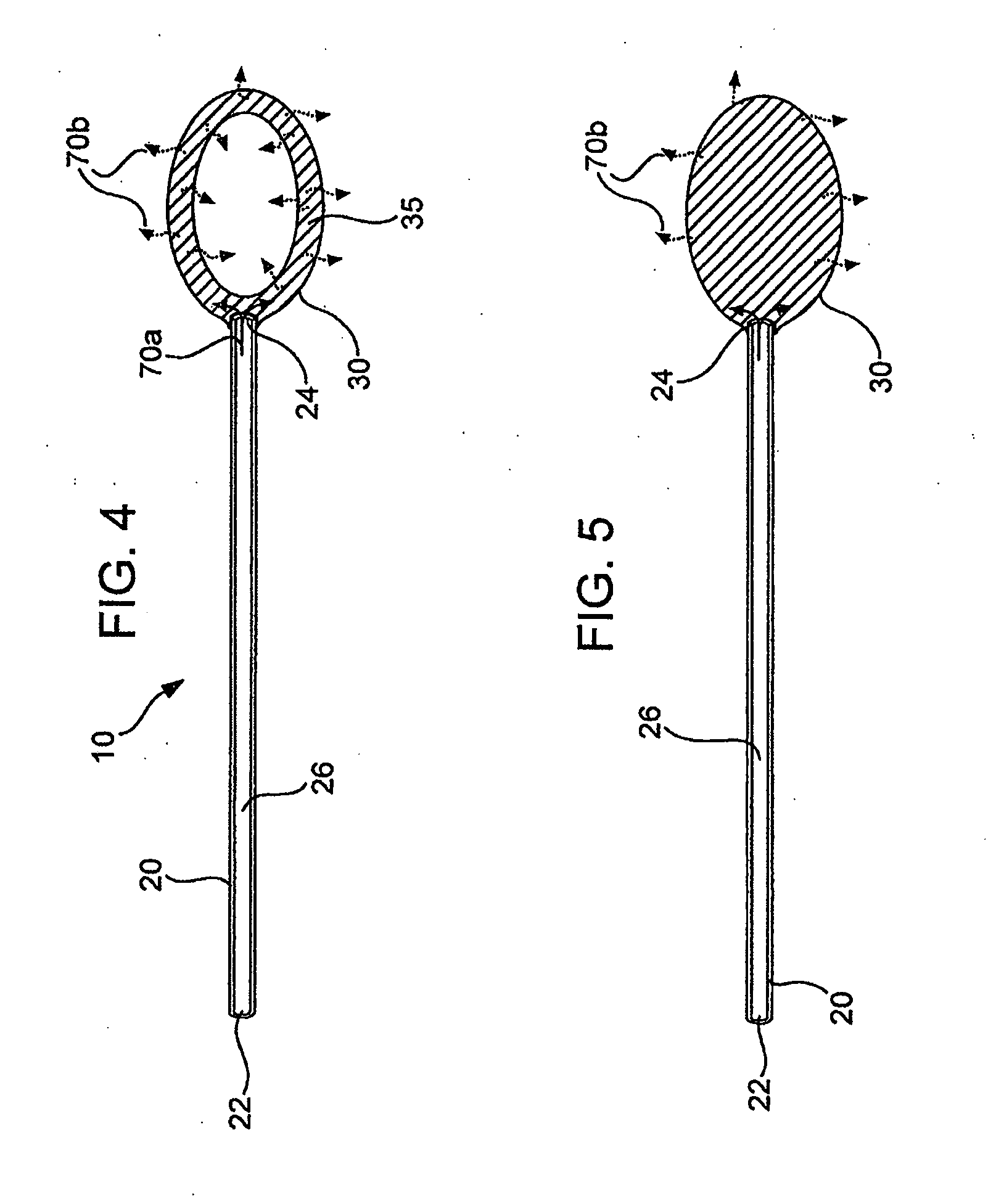
The present invention provides a local concentration management system for delivering a highly concentrated therapeutic agent to a desired delivery site in a subject. The system includes an elongate body with a lumen and a diffuser element, or a dilutor element, that can selectively permeable to the agent. The diffuser element can be attached to the elongate body in various configurations, such as attachment along the elongate body, attachment at the distal end of the elongate body, or a separate structure in fluid communication with the elongate body. The device can be implanted at a desired delivery site and used to deliver formulations comprising high concentrations of the agent with minimal detriment to the surrounding tissue. The system also provides a mechanism for delivering the agent over a greater surface area compared to conventional devices.

Problems solved by technology

Precise and accurate delivery of drugs or therapeutic agents to a specific treatment site within a subject represents a substantial challenge in the design of drug delivery systems.
Site-specific drug delivery can be particularly challenging when the drug is to be delivered to the subject long-term, e.g., over several hours to several days, weeks or months.
While these implantable systems avoid the need for repeated injections often associated with long-term drug therapy administration, they have a number of limitations.
First, the treatment sites which they can access are limited.
Second, sites to which drug delivery is required can be fragile, sensitive or inaccessible and thus often not amenable to insertion of an implant.
Third, the size of the delivery device can be impractical for long-term treatment regimes as the reservoir of the device that holds the drug either needs to be large enough to hold sufficient quantities of drug for the course of treatment or, alternatively, allow re-filling with drug during the course of the treatment.
The latter is especially troubling as manipulating, re-filling and re-positioning these implantable devices can have serious consequences, e.g., increased risk of infection, patient discomfort, and increased costs.
This configuration allows access to previously inaccessible sites, but these devices face many of the same issues as the traditional drug delivery devices, such as catheter size and toxicity at the delivery site.
While this approach has met with some success, there are still serious limitations for certain therapeutics and for chronic delivery.
For example, formulations with high concentrations of drug can be toxic to cells at the delivery site, or can result in irritation, inflammation, and tissue damage at the delivery site.
Often formulating drugs at such high concentrations requires the use of very high or very low pH solutions, which alone can cause adverse side effects, particularly at the delivery site.

Method used


Image

  • Local concentration management system
  • Local concentration management system
  • Local concentration management system

Examples


example 1

Polymeric Cup as Diffuser Element

[0139] Polymeric film is shaped into a diffuser element having a “cup” or “hat” configuration, and is placed over an exit outlet of a drug delivery device, such that the elongate body of the device is actually contained within the body of the drug delivery device (FIG. 8). The diffuser element serves as a secondary rate control means, and capture bursts of formulation that may be released from the drug delivery device.

[0140] The following is an estimate of normalized permeability of suitable polymeric materials for such polymeric diffuser elements for use in delivery of a sufentanil formulation from a drug delivery device, e.g., an osmotic pump. The following assumptions were made in calculating the permeablities of the polymeric materials: [0141] Minimum release rate of agent from device: 2.5 μg / hr [0142] Maximum release rate of agent from device: 20 μg / hr [0143] Diffuser element configuration and dimensions: a cylinder having a diameter of 0.3 cm...

example 2

Delivery of Baclofen HCl

[0149] A Baclofen HCl solution in DMSO (335.8 mg / cc) was delivered using a prototype of a catheter of the invention. With reference to the equations described herein, the dilution ratio was calculated, with Co=335.8 mg / cc Baclofen, with KΠo=31.3:1 mils / cm2 hr for the Silastic tubing (Dow Corning Q 4750). The outer diameter of the tubing (OD) was 0.047 in (0.0597 cm), while the inner diameter was inner diameter (ID) was 0.025 in (0.0317 cm). The mean diameter (calculated by taking the log average value due to variations in wall thickness) was 0.0443 cm, with a tubing wall thickness of 11 mils (0.0235 in minus 0.0125 in). The pumping rate was 20 μl / day (0.083 μl / hr). The length of the elongate body catheter was 5.22 cm.

[0150] Using these values and Equation (2) above, Φo is calculated to be 4.13 :l / hr. Using this value in Equation (3), the estimated flow rate at the exit of the Silasitc tubing (elongate body) should be Fι=0.083 (1+2×4.13 / 0.083)1 / 2=0.83:l / hr. ...


PUM


Abstract

The invention provides a local concentration management system (LCMS) for delivery of highly concentrated therapeutic agent formulations. The LCMS comprises a device comprising an elongate body defining a lumen between its proximal and distal ends, and a diffuser element, a dilutor element, or both. The diffuser element, which is selectively permeable to the agent, is operatively associated with the elongate body so that agent flows through the elongate body, and into and through the diffuser element to exit the system. The dilutor element can be operatively associated with the system to be in fluid communication with the elongate body lumen, a diffusion space defined by a diffuser element inner wall, or both. The dilutor element is selectively water permeable, but substantially impermeable to agent, to provide for dilution of the agent during transit through the system. The LCMS system is designed to disperse and / or dilute the drug delivery stream.

Description

FIELD OF THE INVENTION [0001] This invention relates generally to drug delivery devices and methods of use relating to same, and more particularly relates to a device suitable for delivery of highly concentrated agent formulations. BACKGROUND OF THE INVENTION [0002] Precise and accurate delivery of drugs or therapeutic agents to a specific treatment site within a subject represents a substantial challenge in the design of drug delivery systems. Site-specific drug delivery can be particularly challenging when the drug is to be delivered to the subject long-term, e.g., over several hours to several days, weeks or months. [0003] One approach to long-term site-specific drug delivery involves the use of implantable delivery systems, e.g., biodegradable or osmotically-driven drug delivery devices (see e.g., U.S. Pat. Nos. 5,607,696, 5,609,885, and 5,783,213. While these implantable systems avoid the need for repeated injections often associated with long-term drug therapy administration, ...

Claims


Application Information

Patent Timeline
Patent Type & Authority Applications(United States)
IPC IPC(8): A61K9/22A61M25/00A61M25/14A61M25/16
CPCA61M25/00A61M25/0043A61M2025/1086A61M2025/105A61M2025/0057
Inventor THEEUWES, FELIXYUM, SU
Owner DURECT CORP
Learn More