
Internal combustion engine

a technology of internal combustion engine and combustion engine, which is applied in the direction of combustion engine, lubrication element, pressure lubrication, etc., can solve the problems of relatively complex structure of internal combustion engine, malfunction of exhaust turbocharger, etc., and achieve the effect of reducing the required installation spa

Inactive Publication Date: 2013-07-02
DR ING H C F PORSCHE AG
View PDF29 Cites 6 Cited by
  • Summary
  • Abstract
  • Description
  • Claims
  • Application Information

AI Technical Summary

Benefits of technology

The invention provides an internal combustion engine without the need for bypass lines, which simplifies the engine's structure. The engine uses a pressure limiting device that reduces the risk of damage to the exhaust turbochargers due to excessive vacuum. The pressure limiting device can be integrated into the oil pump to save installation space.

Problems solved by technology

Moreover, an excessive vacuum could lead to a malfunction of the exhaust turbocharger.
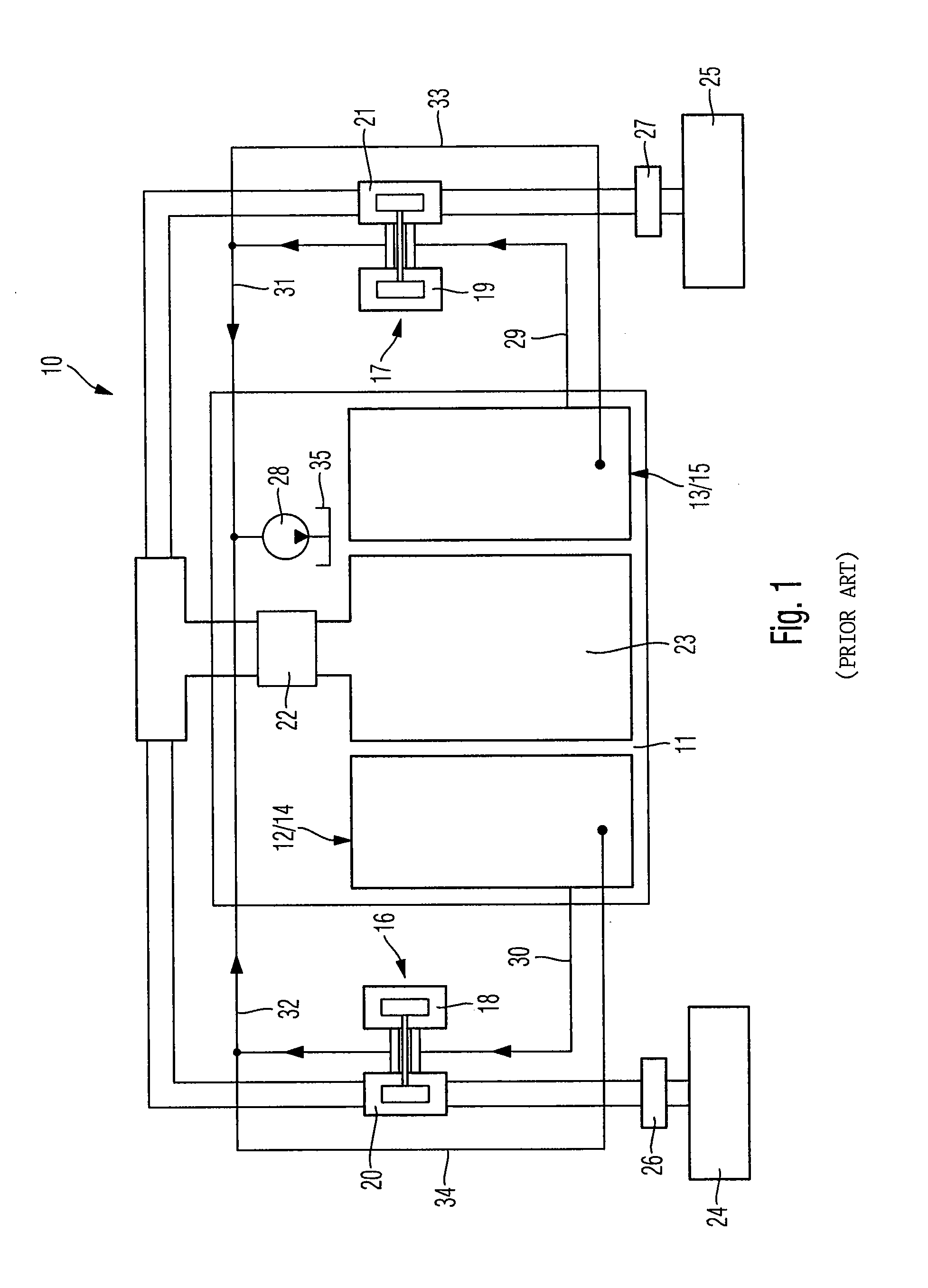
However, these bypass lines 33 and 34 make the structure of an internal combustion engine relatively complex.

Method used


Image

  • Internal combustion engine
  • Internal combustion engine
  • Internal combustion engine

Examples


Embodiment Construction

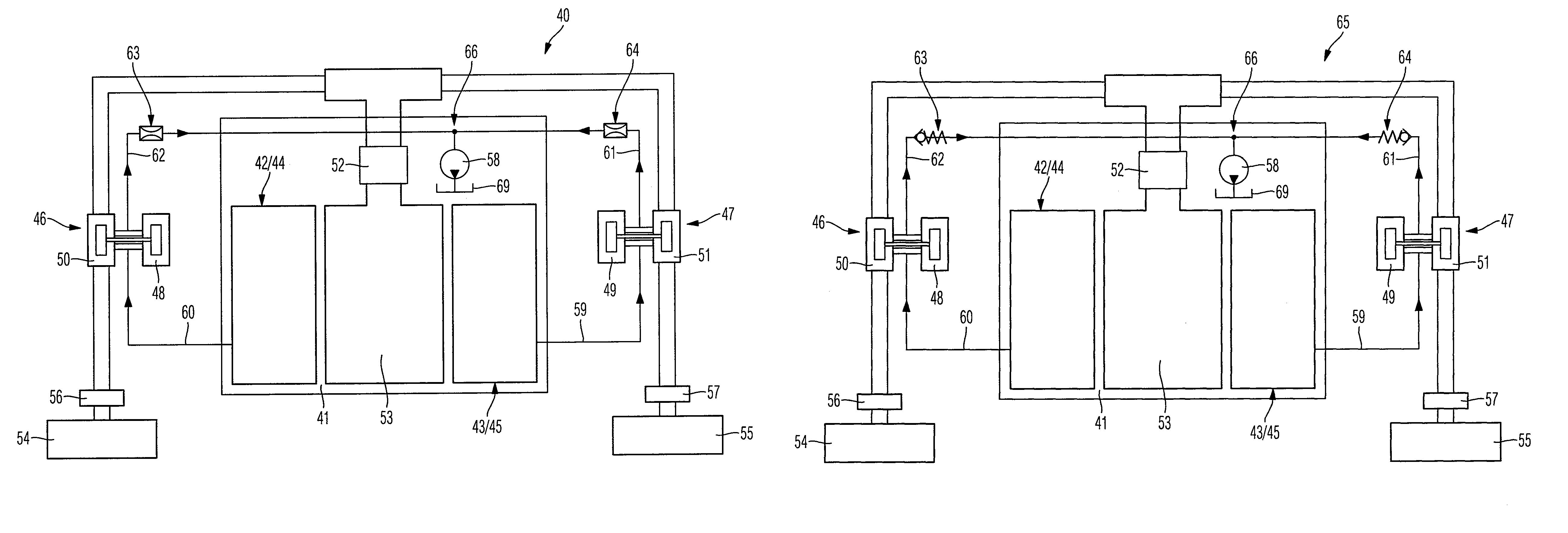
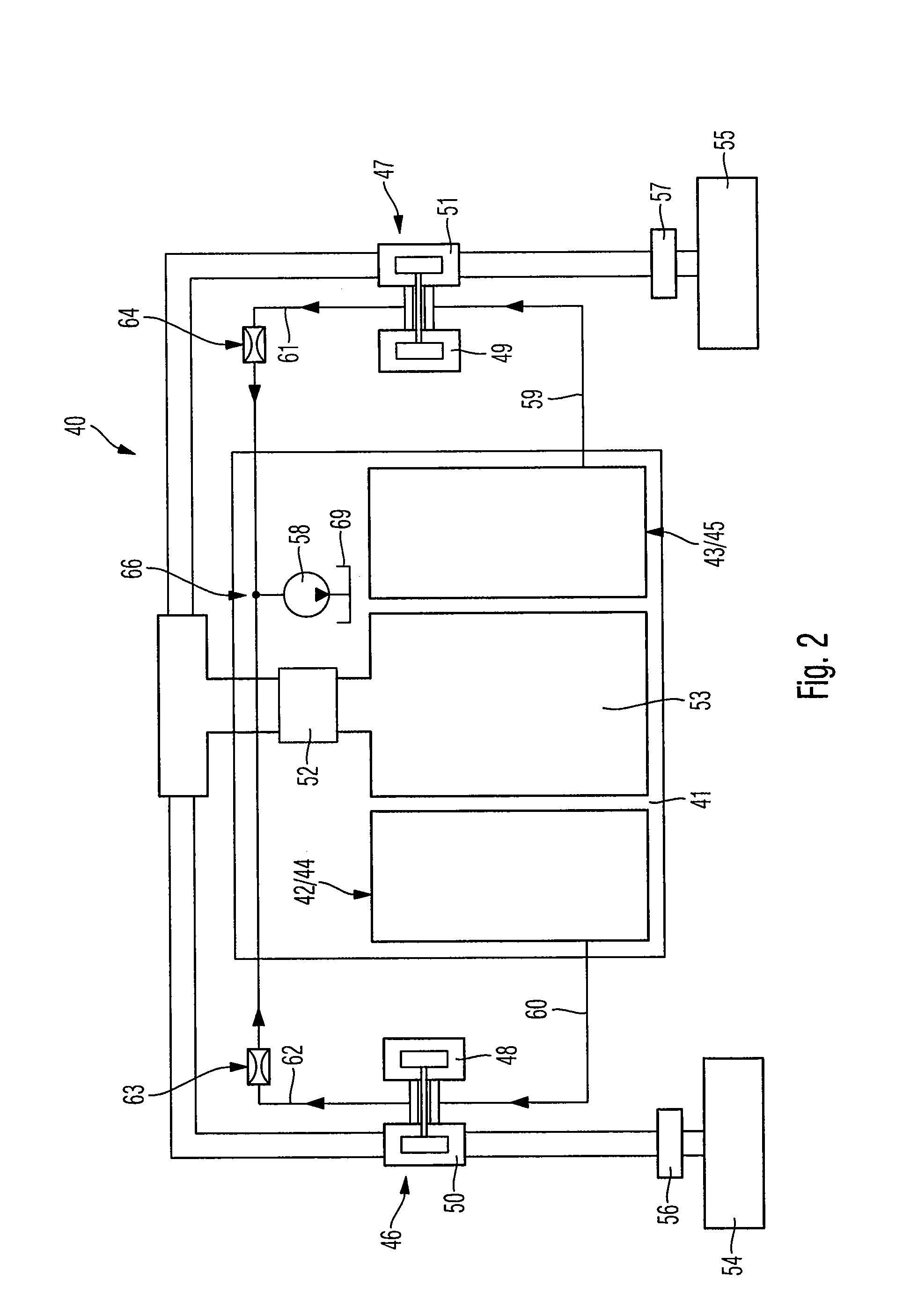
[0019]FIG. 2 shows a highly schematized block diagram of a preferred illustrative embodiment of an internal combustion engine 40 according to aspects of the invention, which is again used to accommodate cylinders (not shown in detail) by means of a crankcase 41. FIG. 2 again shows just two cylinder groups 42 and 43 with the corresponding cylinder head housings 44 and 45 of the cylinder groups 42 and 43.

[0020]Interacting with each cylinder group 42 and 43 there is again an exhaust turbocharger 46 and 47, respectively, and of the exhaust turbochargers 46 and 47 the figure again shows the turbines 48 and 49 and the compressors 50 and 51. The turbines 48 and 49 are used for expansion of an exhaust gas flow from the internal combustion engine, namely an exhaust gas flow from the respective cylinder groups 42 and 43, the turbines 48 and 49 of the exhaust turbochargers 46 and 47 driving the respective compressors 50 and 51 of the respective turbochargers 46 and 47 in order to compress a co...


PUM


Abstract

An internal combustion engine includes a crankcase which accommodates cylinders, having at least one exhaust turbocharger and having an oil circuit containing at least one oil pump, in which engine oil is siphoned by at least one oil pump and delivered to the cylinders for lubrication, and in which the or each exhaust turbocharger is coupled to the oil circuit such that siphoned engine oil can be distributed to bearings of the respective turbocharger via an inlet line leading to the respective exhaust turbocharger and can then be expelled from the bearings of the respective exhaust turbocharger in the direction of an oil sump via an outlet line leading away from the respective exhaust turbocharger. The respective outlet line of the respective exhaust turbocharger is assigned a pressure limiting device, with the aid of which a vacuum prevailing at the bearings of the respective exhaust turbocharger can be limited.

Description

CROSS REFERENCE TO RELATED APPLICATIONS[0001]This U.S. application claims priority to German Application No. DE 10 2009 051848.7, filed on Oct. 28, 2009, which is incorporated by reference herein in its entirety.FIELD OF THE INVENTION[0002]The invention relates to an internal combustion engine.BACKGROUND OF THE INVENTION[0003]FIG. 1 shows a schematized block diagram of an internal combustion engine 10 known from the prior art, the internal combustion engine 10 known in practice comprising a crankcase 11, which accommodates cylinders (not shown in detail) of the internal combustion engine 10. The cylinders of the internal combustion engine 10 form two cylinder groups 12, 13, and there is a cylinder head housing 14 and 15, respectively, for each cylinder group 12, 13. Interacting with each cylinder group 12, 13 of the internal combustion engine 10 there is an exhaust turbocharger 16 and 17, respectively, and of the two exhaust turbochargers 16 and 17 the figure shows a turbine 18 and ...

Claims


Application Information

Patent Timeline
Patent Type & Authority Patents(United States)
IPC IPC(8): F02B33/44F01M9/00F01M1/12F01D25/18F02B39/14
CPCF01M1/12F01M11/02F02B39/14F01M2011/021F02B37/007
Inventor KISTNER, BRUNOFREIERMUTH, BERNHARDMULLER, CHRISTOPH
Owner DR ING H C F PORSCHE AG
Learn More