Capacitive liquid-level sensor
a liquid level sensor and capacitive technology, applied in liquid/fluent solid measurement, instruments, machines/engines, etc., can solve the problems of large scale and complex operation of liquid level calculation devices, and achieve the effect of accurate detection of liquid level and easy access to highly sensitive liquid level sensors
- Summary
- Abstract
- Description
- Claims
- Application Information
AI Technical Summary
Benefits of technology
Problems solved by technology
Method used
Image
Examples
embodiment 1
[0115]A liquid level sensor according to Embodiment 1 of the present invention will be described below with reference to the accompanying drawings.
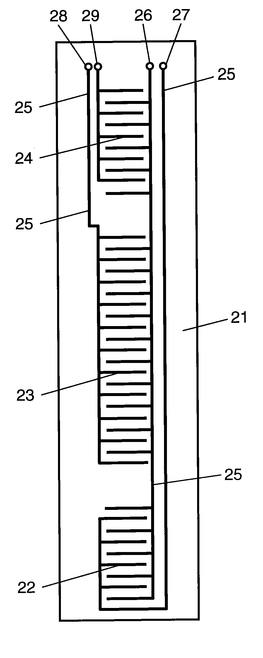
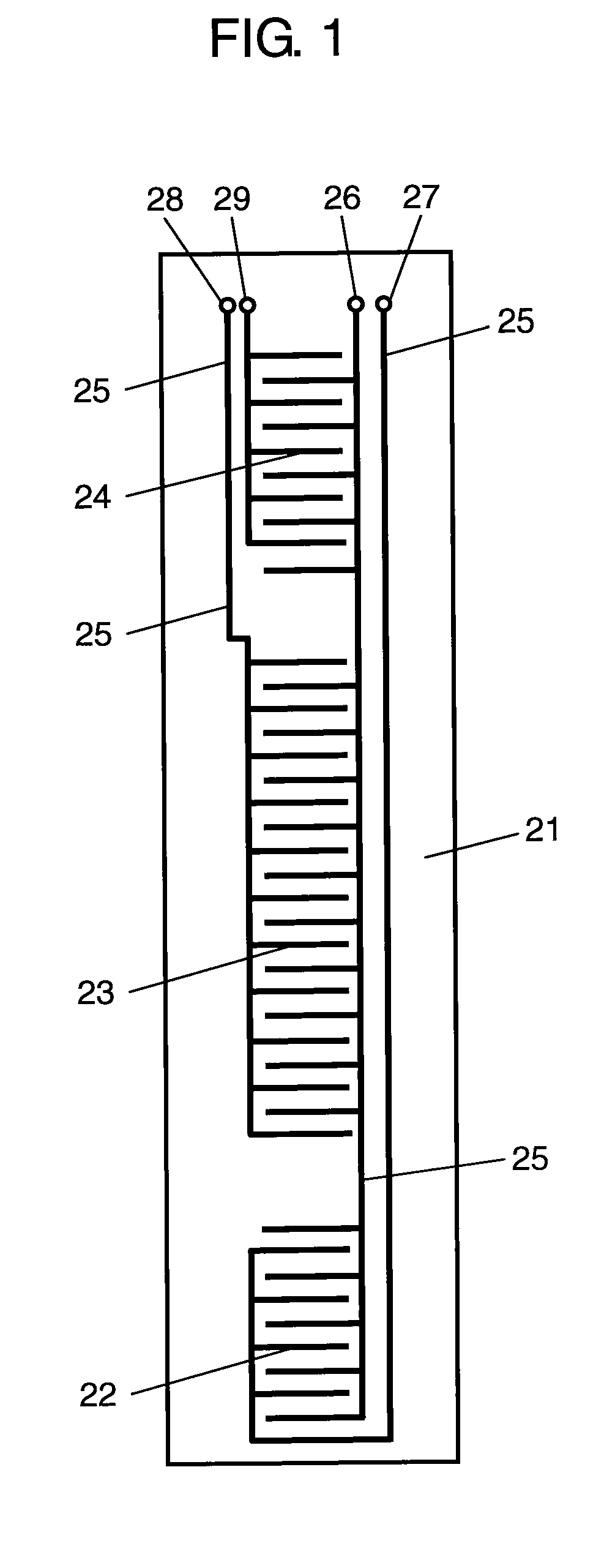
[0116]FIG. 1 is a front view of a detecting unit in the liquid level sensor according to Embodiment 1 of the present invention. In FIG. 1, a pair of first comb-shaped detecting electrodes 22 made of carbon are arranged on a lower end portion of vertically extending rectangular detecting unit 21 made of a polyimide film or the like. A pair of second comb-shaped detecting electrodes 23 made of carbon are arranged at the center of detecting unit 21. Furthermore, similarly, a pair of third comb-like detecting electrodes 24 made of carbon are arranged on an upper end portion of detecting unit 21. First, second, and third detecting electrodes 22, 23, and 24 are connected to terminals 26, 27, 28, and 29 with vertically extending extraction lines 25.
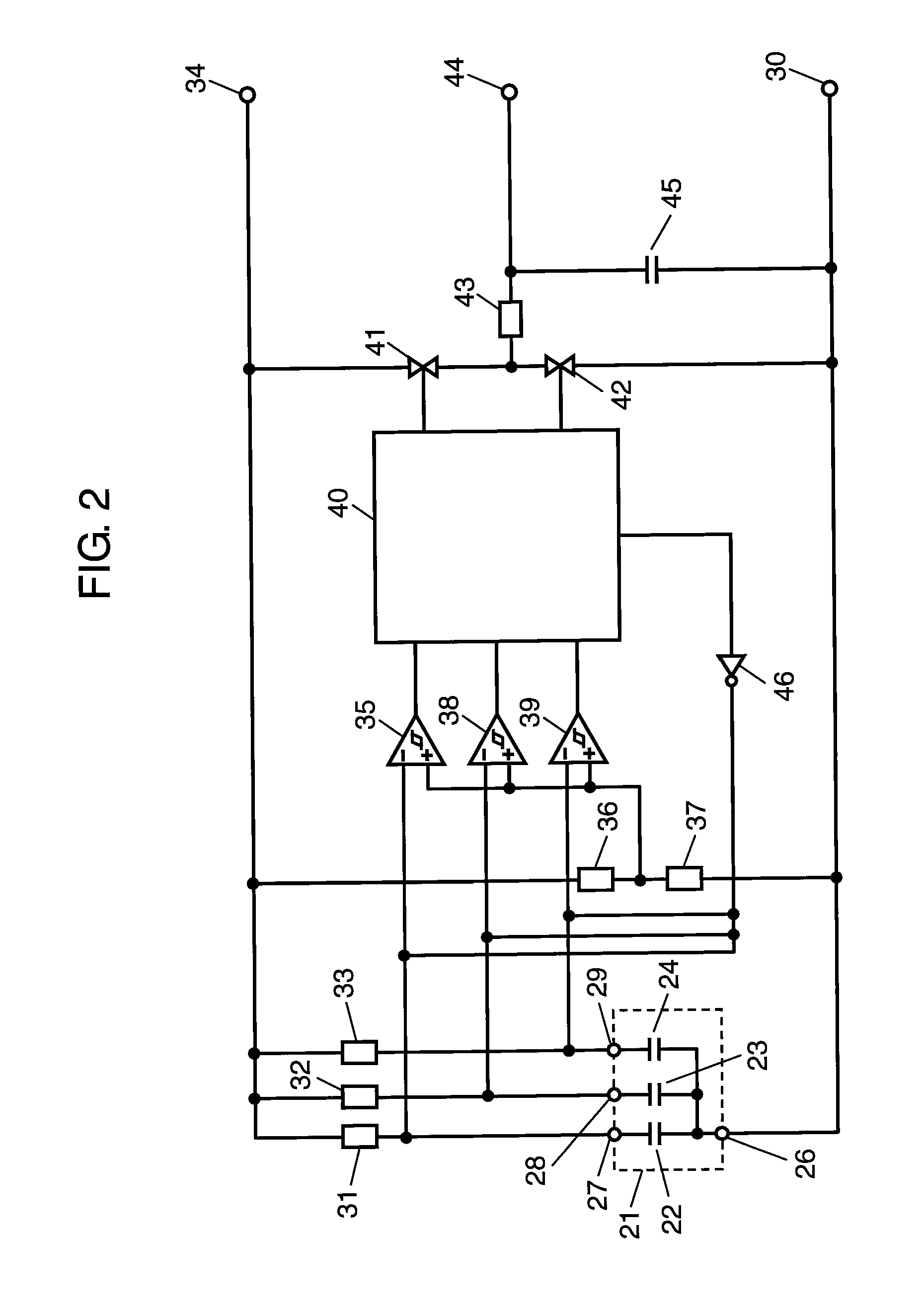
[0117]FIG. 2 is a detecting circuit diagram of the liquid level sensor according to Embodiment 1 o...
embodiment 2
[0172]A liquid level sensor according to Embodiment 2 of the present invention will be described below with reference to the accompanying drawings.
[0173]FIG. 8 is a front view of a detecting unit of the liquid level sensor according to Embodiment 2 of the present invention. In FIG. 8, a pair of first comb-shaped detecting electrodes 222 made of carbon are arranged on a lower end portion of vertically extending rectangular detecting unit 221 made of a polyimide film or the like. A pair of second comb-shaped detecting electrodes 223 made of carbon are arranged at the center of detecting unit 221. Furthermore, similarly, a pair of third comb-shaped detecting electrodes 224 made of carbon are arranged on an upper end portion of detecting unit 221. First, second, and third detecting electrodes 222, 223, and 224 are connected to terminals 229, 230, 231, and 232 by common extraction line 225 and extraction lines 226, 227, and 228 which vertically extend. First cancel electrode 233 arranged...
embodiment 3
[0234]A liquid level sensor according to Embodiment 3 of the present invention will be described below.
[0235]FIG. 15 is a front view of a detecting unit in the liquid level sensor according to Embodiment 3 of the present invention. In FIG. 15, a pair of first comb-shaped detecting electrodes 322 made of carbon are arranged on a lower portion of vertically extending rectangular detecting unit 321 made of a polyimide film or the like. Above first detecting electrodes 322, a pair of second comb-shaped detecting electrodes 323 made of carbon are arranged. Above second detecting electrodes 323, similarly a pair of third comb-shaped detecting electrodes 324 made of carbon are similarly arranged. Further, a pair of fourth comb-shaped detecting electrodes 325 made of carbon are similarly arranged on a lower end portion of detecting unit 321. First, second, third, and fourth detecting electrodes 322, 323, 324, and 325 are connected to terminals 326, 327, 328, 329, and 330 with vertically ext...
PUM
 Abstract
Description
Claims
Application Information
 - R&D
- Intellectual Property
- Life Sciences
- Materials
- Tech Scout
- Unparalleled Data Quality
- Higher Quality Content
- 60% Fewer Hallucinations
Browse by: Latest US Patents, China's latest patents, Technical Efficacy Thesaurus, Application Domain, Technology Topic, Popular Technical Reports.
© 2025 PatSnap. All rights reserved.Legal|Privacy policy|Modern Slavery Act Transparency Statement|Sitemap|About US| Contact US: help@patsnap.com


