Floating brake disc

a technology of brake discs and brake discs, which is applied in the direction of brake systems, railway braking systems, mechanical devices, etc., can solve the problems of brake disc breakage, to occur, connective devices are exposed to wear and tear, and manufacture is very expensive, so as to improve the flow of force, and reduce the overall wear of the brake dis

Inactive Publication Date: 2013-07-02
SPACEK STANISLAV
View PDF8 Cites 6 Cited by
  • Summary
  • Abstract
  • Description
  • Claims
  • Application Information

AI Technical Summary

Benefits of technology

[0009]The advantage of the invention is that the transmission of force is apportioned to the connecting means and to the bearing surface which is established by the projection and the indentation. The forces that occur when the brake disc is in operation are distributed both via the connecting means and via the bearing surface established by the projection and the indentation. This has the advantage that manufacture needs to take place, otherwise than is the case in U.S. Pat. No. 6,957,726 B2, in a far less precise manner and that, as a result of the additional load-bearing of the connecting means, the wearing of the brake disc as a whole is reduced.
[0010]In one preferred embodiment, there is a clearance between the projection and the indentation, so that the outer ring and inner ring do not constantly bear against one another in this region, but the bearing surface is formed only as a result of relative movement of the inner ring and outer ring. This means that the bearing surface is formed only when the inner ring and outer ring move relative to one another. This is the case, for example, during the decelerating operation or as a result of a gyratory transverse movement.
[0011]In the course of unbraked operation, it is preferable if the bearing surface between the projection and the indentation is not formed, if the at least one connecting means merely trails. This means that, in the unbraked condition, all transmissions of force take place via the connecting means. During the braking operation, however, in which particularly high forces occur, the bearing surface between the inner ring and the outer ring is formed, and a frictional contact connection occurs between the said parts. The forces in the braking operation are thereby apportioned to the connecting means and the bearing surface. As a result of this measure, the connecting means may be of less robust design than in the case of ordinary floating brake discs belonging to the prior art.
[0012]According to one preferred embodiment, the shape of the projection may be described as being in the form of a nose or beak. The projection on the inner ring preferably extends radially at the point where it encounters the indentation in the outer ring. This means that one side or edge of the projection on the inner ring is of radial construction. In this connection, “radial” is understood to mean that the edge of the projection lies on a radius of the brake disc as a whole or of the inner ring, or on a prolongation of the radius of said inner ring. As a result of this measure, a radial bearing surface between the inner ring and the outer ring is formed. According to another preferred embodiment, the rotor has, in the region of the projection, at least one perforation, which could also be described as a “hole”. The said perforation is, in particular, wedge-shaped, and can also be described as “triangular”, one side of the said triangle or wedge extending, in particular, parallel to the edge of the projection which forms, together with the corresponding region of the indentation in the outer ring, the bearing surface according to the invention. The perforations follow the shape of the projection. The corners of the perforations are preferably rounded. This formation according to the invention brings about an improved flow of force within the inner ring. The forces acting upon the projection, and therefore upon the inner ring, after the forming of the bearing surface, for example during the braking operation, are conducted into the inner ring in such a way, as a result of the preferred configuration of the perforations, that the most favourable possible distribution of the forces that occur can take place.
[0013]According to another preferred embodiment, the corners of the indentation, which is constructed in the outer ring, are rounded. As a result of this measure, the flow of force within the brake disc, or more precisely within the outer ring of said brake disc, is further improved.
[0014]These and other aspects of the present invention are realized in a brake disc as shown and described in the following figures and related description.

Problems solved by technology

A problem with regard to the durability of floating brake discs is constituted by the connecting means, which are acted upon by powerful forces during the braking operation, so that it is possible, in some cases, for shearing-off of the connecting means, and thereby breakage of the brake disc, to occur.
In any case, the connecting means are exposed to wear and tear.
Thus, manufacture is very expensive since the sections of toothing have to be manufactured accurately in order to make the desired meshing, and the relieving of the load on the connecting means, possible at all.
The constant subjection of the bearing surface to load in the region of the toothing between the inner and outer rings results in a relatively high degree of wear.

Method used


Image

  • Floating brake disc
  • Floating brake disc

Examples


Embodiment Construction

[0020]The invention and accompanying drawings will now be discussed in reference to the numerals provided therein so as to enable one skilled in the art to practice the present invention. The drawings and descriptions are exemplary of various aspects of the invention and are not intended to narrow the scope of the appended claims.

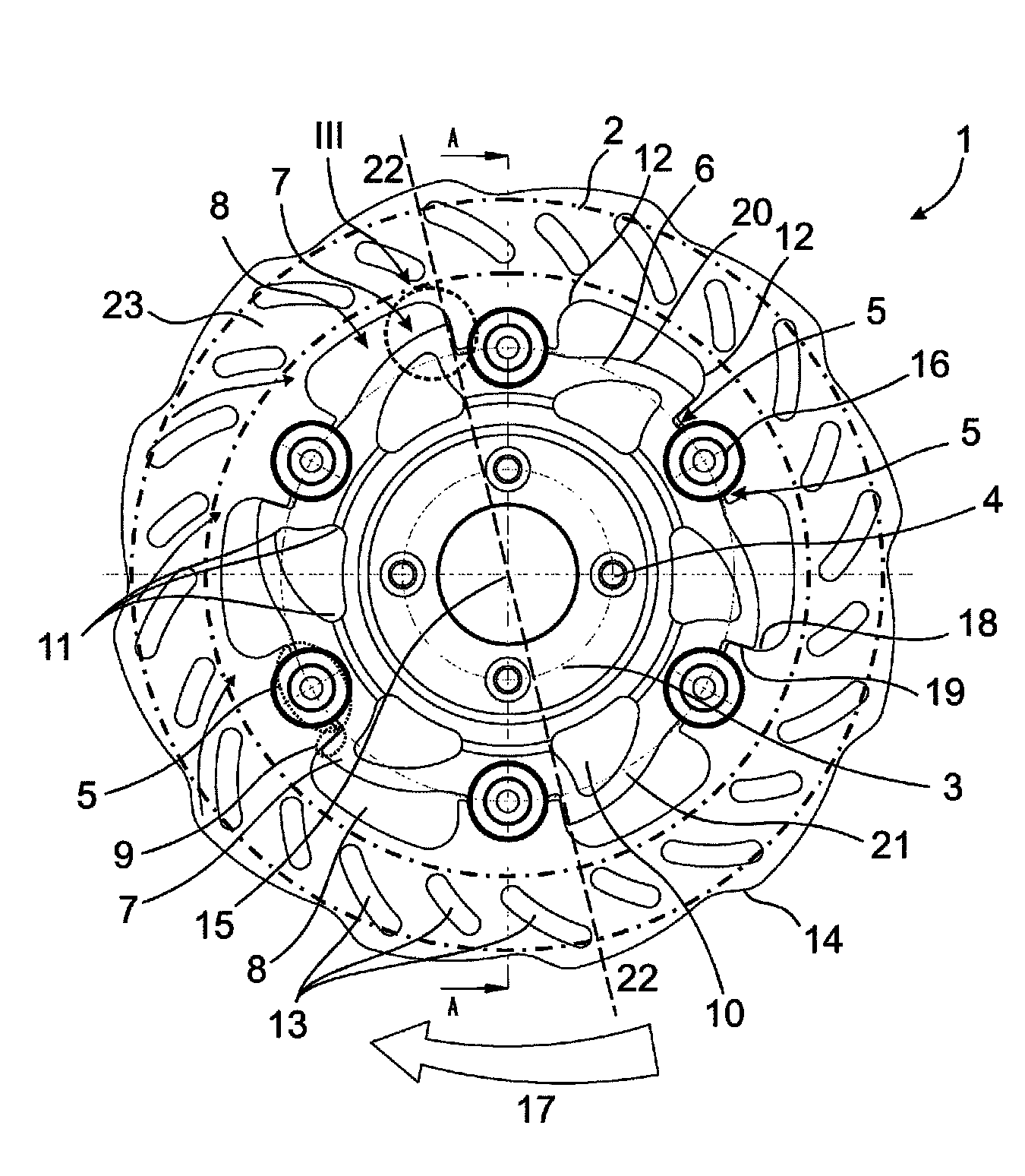
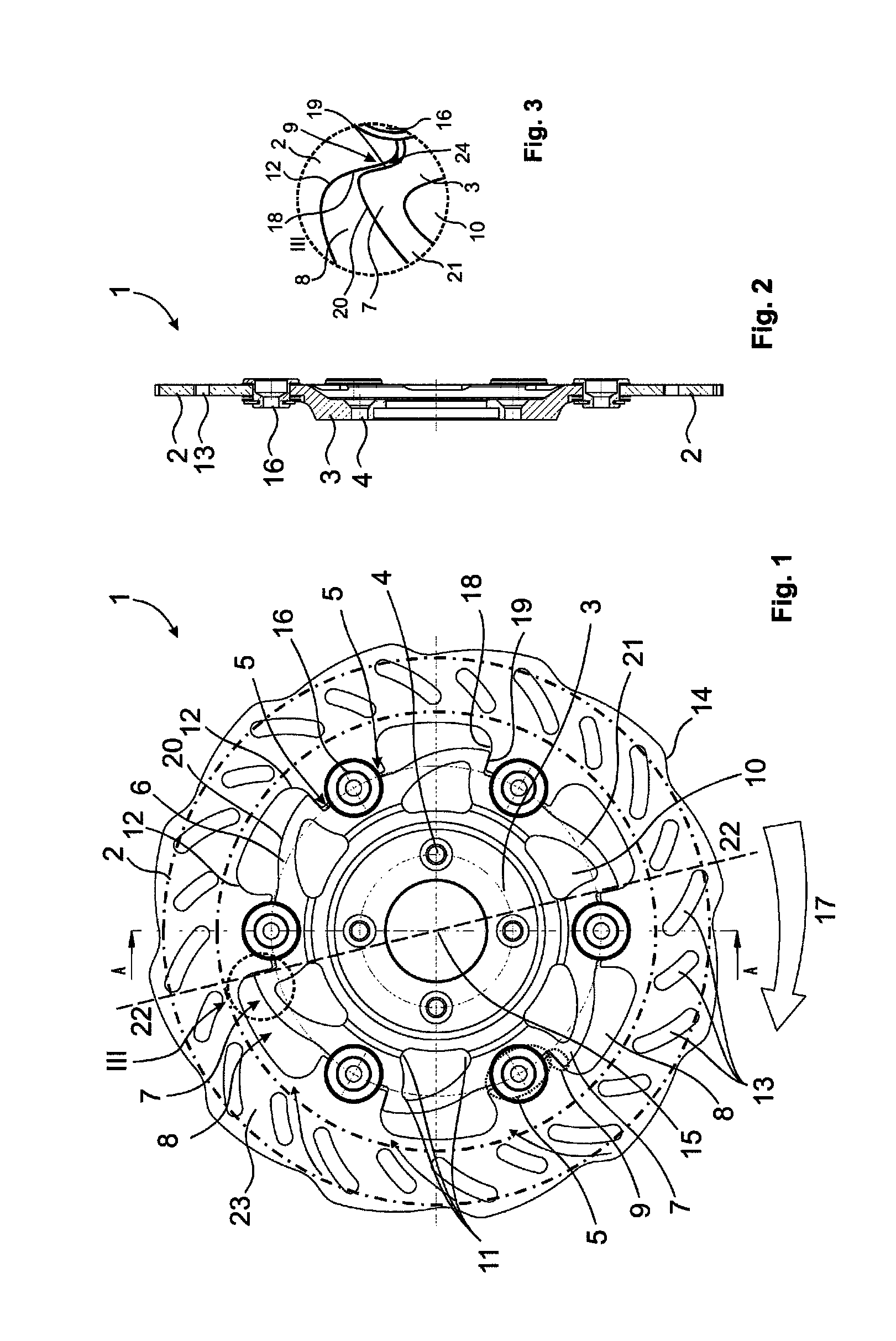
[0021]A floating brake disc 1 according to the invention is represented in FIGS. 1 and 2, whereas FIG. 3 shows the detail III in enlarged form. The brake disc represented is preferably intended for use in a motorcycle. It has an inner ring 3 and an outer ring 2. Located on the outer ring is the brake band 23, that is to say the region on which the brake pad of the vehicle's brake runs. The brake band is indicated in chain-dotted lines in the representation. Provided in the centre of the inner ring 3 are bores 4, via which coupling to a wheel of the vehicle takes place with the aid of fastening means (not represented).

[0022]According to the invention, a cont...


PUM


Abstract

The invention relates to a floating brake disc (1), particularly for a motorcycle, particularly an off-road motorcycle, which comprises an outer ring (2) which carries a brake band (23) and an inner ring (3) via which the brake disc (1) is connected to a wheel of the vehicle. According to the invention, at least one region (5) of contact, in particular a number of regions (5) of contact, between the outer ring (2) and the inner ring (3) is / are formed on a circular arc (6) extending, concentrically with the brake disc (1), between the outer ring (2) and the inner ring (3), the outer ring (2) and inner ring (3) being connected to one another in the at least one contact region (5) with at least one connecting means (16), in particular a rivet. The inner ring (3) also has, next to the at least one contact region (5), a projection (7) which engages in an indentation (8) in the outer ring (2) in such a way that a bearing surface (9) between the inner ring (3) and the outer ring (2) can be formed, at least when the brake disc (1) is in operation in a vehicle, particularly a motorcycle.

Description

PRIORITY[0001]The present application claims the benefit of EP 08163254.9, filed Aug. 29, 2008, which is herein incorporated by reference in its entirety.THE FIELD OF THE INVENTION[0002]The present invention relates to a floating brake disc, particularly for a motorcycle.BACKGROUND[0003]The term “floating brake disc” describes a two-part brake disc. A floating brake disc consists of an inner ring and an outer ring, which are coupled to one another via connecting means. The inner ring is also described as a “carrier pot”, and the outer ring as a “braking rim” or as a “rotor”. The outer ring carries the brake band, that is to say, the brake linings run on said ring. Coupling to the wheel takes place via the inner ring. Floating brake discs were developed in order to avoid overheating problems in one-piece brake discs. A problem with regard to the durability of floating brake discs is constituted by the connecting means, which are acted upon by powerful forces during the braking operat...

Claims


Application Information

Patent Timeline
Patent Type & Authority Patents(United States)
IPC IPC(8): F16D65/12
CPCF16D65/12F16D2065/026F16D2065/136F16D2065/1392
Inventor SPACEK, STANISLAV
Owner SPACEK STANISLAV
Why Eureka
Try Eureka