Refractive index distribution measuring method and apparatus, and method of producing optical element thereof, that use multiple transmission wavefronts of a test object immersed in at least one medium having a different refractive index from that of the test object and multiple reference transmission wavefronts of a reference object having known shape and refractive index distribution

a technology of refractive index and measurement method, applied in the field of apparatus and a method for measuring the refractive index distribution of an object, can solve the problems of unsatisfactory refractive index, difficult to accurately measure the placement of the object, and inability to achieve desired optical characteristics. to achieve the effect of accurately calculating the refractive index distribution of the obj

Inactive Publication Date: 2013-07-02
CANON KK
View PDF35 Cites 0 Cited by
  • Summary
  • Abstract
  • Description
  • Claims
  • Application Information

AI Technical Summary

Benefits of technology

[0008]The present invention provides a refractive index distribution measuring method and a refractive index distribution measuring apparatus capable of accurately calculating the refractive index distribution of the object, without requiring highly accurate placement of the object in the medium, and provides a method of producing an optical element.

Problems solved by technology

However, the molding forming technique may cause unevenness of the refractive index in the optical element depending on forming conditions.
Such unevenness of the internal refractive index may provide significant influences on optical characteristics of the optical element, which makes it impossible to achieve desired optical characteristics.
However, when the object has a complex shape like an optical element such as a lens, it is difficult to accurately measure the placement of the object, which makes it difficult to accurately calculate the refractive index distribution of the object.

Method used


Image

  • Refractive index distribution measuring method and apparatus, and method of producing optical element thereof, that use multiple transmission wavefronts of a test object immersed in at least one medium having a different refractive index from that of the test object and multiple reference transmission wavefronts of a reference object having known shape and refractive index distribution
  • Refractive index distribution measuring method and apparatus, and method of producing optical element thereof, that use multiple transmission wavefronts of a test object immersed in at least one medium having a different refractive index from that of the test object and multiple reference transmission wavefronts of a reference object having known shape and refractive index distribution
  • Refractive index distribution measuring method and apparatus, and method of producing optical element thereof, that use multiple transmission wavefronts of a test object immersed in at least one medium having a different refractive index from that of the test object and multiple reference transmission wavefronts of a reference object having known shape and refractive index distribution

Examples


embodiment 1

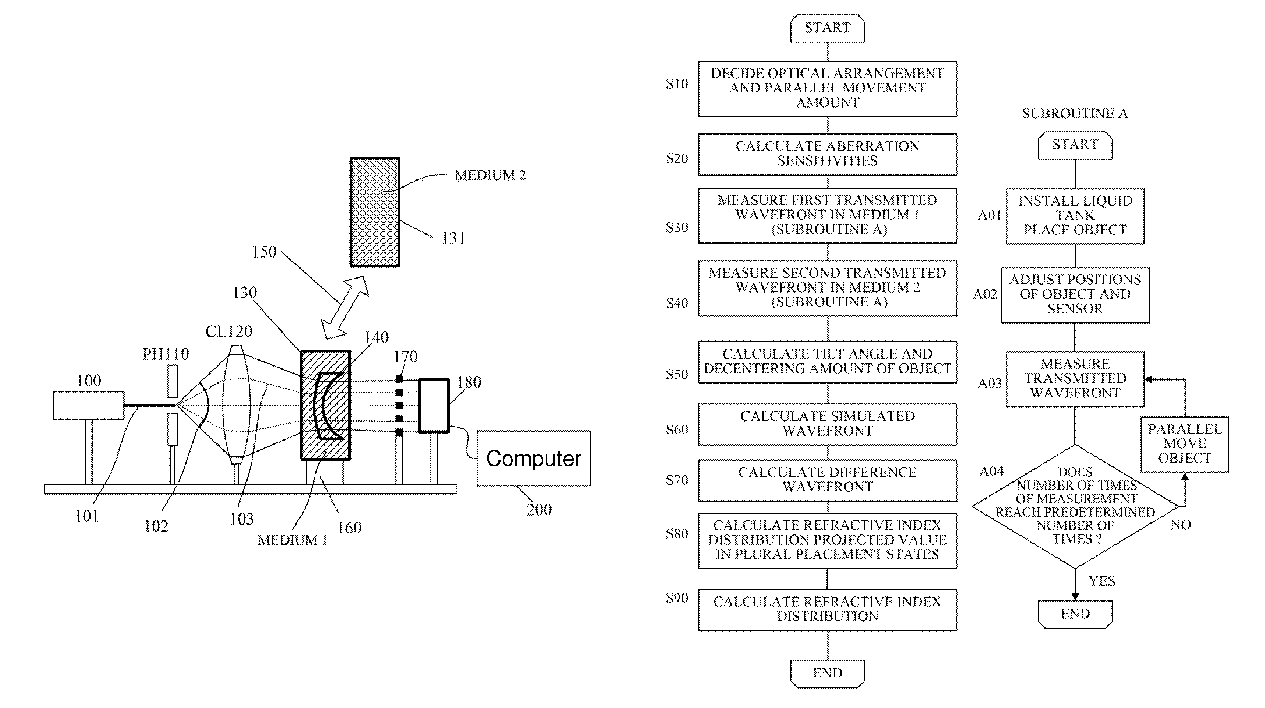
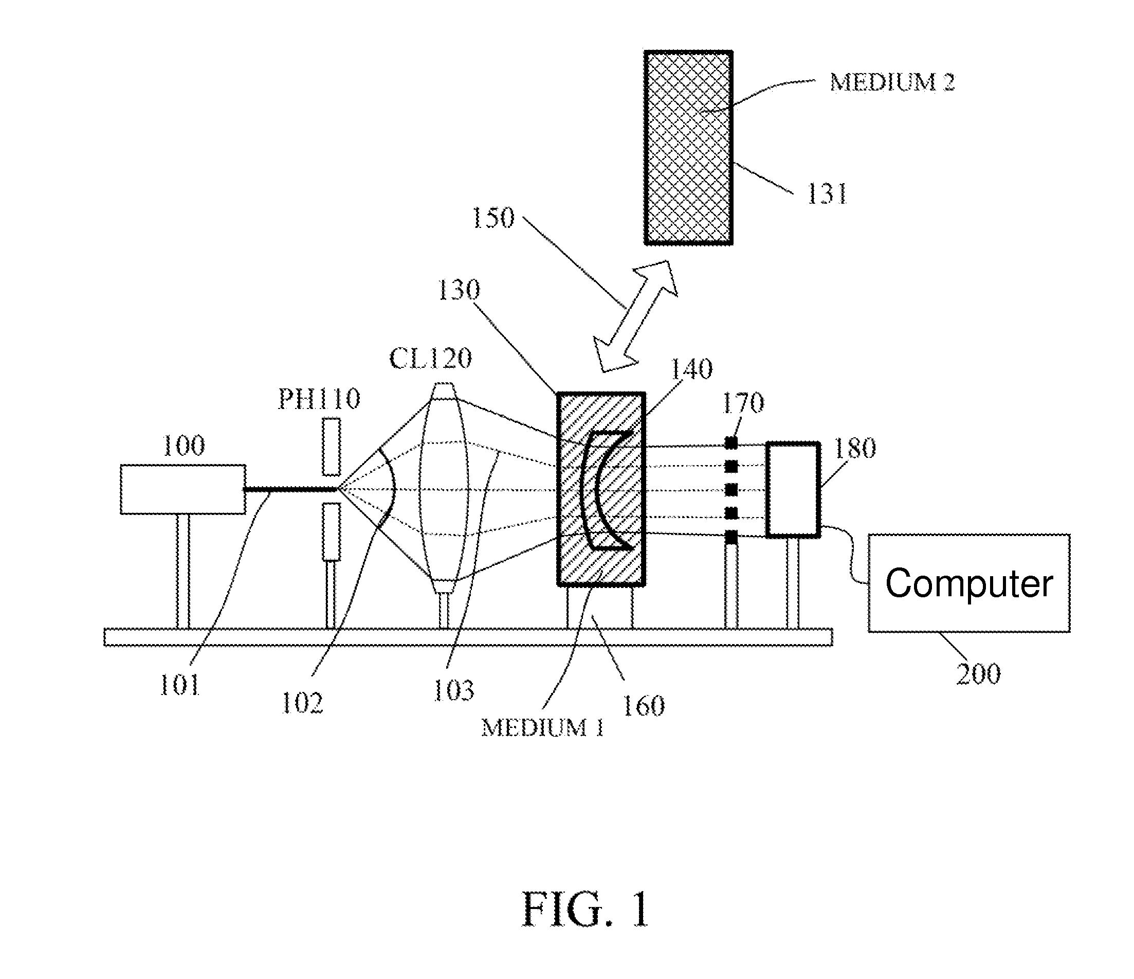
[0023]FIG. 1 shows the configuration of a refractive index measuring apparatus that is a first embodiment (Embodiment 1) of the present invention. This refractive index measuring apparatus measures (calculates) an internal refractive index distribution (hereinafter also simply referred to as “a refractive index distribution”) of an object 140 that is an optical element such as a lens.

[0024]The apparatus causes reference light emitted from a laser light source 100 to enter the object 140 in states where the object 140 is soaked in two media (a first medium such as water and a second medium such as oil) having refractive indices different from each other and from that of the object, to measure a transmitted wavefront of the object 140. Then, a calculating part 200 constituted by a computer calculates the refractive index distribution of the object 140 by using the measured transmitted wavefronts. This embodiment uses a Talbot interferometer as a wavefront sensor to measure the transmi...

embodiment 2

[0105]Description will hereinafter be made of a refractive index distribution measuring apparatus that is a second embodiment (Embodiment 2) of the present invention with reference to FIG. 4. Although Embodiment 1 performs the measurement of the transmitted wavefronts in the states where the object is placed in the two media having mutually different refractive indices, Embodiment 2 performs measurement of transmitted wavefronts in states where an object is placed in a same medium, but two light sources (first reference light and second reference light) having mutually different wavelengths are used.

[0106]A refractive index distribution measuring apparatus shown in FIG. 4 uses a light source 1 (first light source) that is a He—Ne laser (wavelength 633 nm) and a light source 2 (second light source) that emits a second harmonic (wavelength 532 nm) of a YAG laser. The medium in which the object 140 is placed may be, though detailed description will be made below, a medium having a refr...

embodiment 3

[0133]It is possible to feed back the measurement result of the refractive index distribution acquired by the measuring apparatus (or the measuring method) of each of Embodiments 1 and 2 to a method for producing optical elements such as lenses. FIG. 7 shows an example of the method for producing the optical element using mold forming.

[0134]The optical element is produced through a process of designing the optical element, a process of designing a mold and a mold forming process of forming the optical element by using the mold. The formed optical element is evaluated for shape accuracy. If the shape accuracy is deficient, the mold is corrected and then the mold forming process is performed again. If the shape accuracy is sufficient, the optical element is evaluated for optical performance.

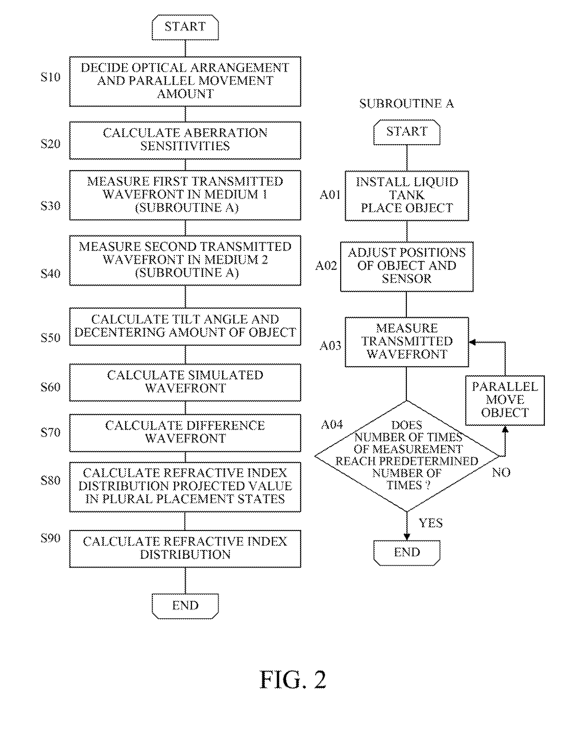
[0135]Incorporating the refractive index distribution measuring procedure described using FIGS. 2 and 6 in this optical performance evaluating process enables mass production of the optical element...


PUM

PropertyMeasurementUnit
refractive index distributionaaaaaaaaaa
refractive indexaaaaaaaaaa

Abstract

The method measures first transmitted wavefronts and second transmitted wavefronts by respectively causing reference light to enter an object placed in plural placement states in a first medium and a second medium, calculates an aberration sensitivity with respect to changes of the placement state of the object, and calculates an alignment error of the object in each placement state by using the aberration sensitivity and the first and second transmitted wavefronts measured in each placement state. The method further calculates first and second reference transmitted wavefronts respectively acquirable when causing the reference light to enter the reference object placed in placement states including the alignment errors in the first medium and the second medium, and calculates a refractive index distribution of the object which a shape component thereof is removed, by using the first and second transmitted wavefronts and the first and second reference transmitted wavefronts.

Description

BACKGROUND OF THE INVENTION[0001]1. Field of the Invention[0002]The present invention relates to an apparatus and a method for measuring a refractive index distribution of an object such as an optical element.[0003]2. Description of the Related Art[0004]Optical elements such as lenses used in optical apparatuses such as digital cameras and laser beam printers require a high refractive index. Moreover, using a mold forming technique makes it easy to form a complex shape such as an aspheric surface from an optical glass and a plastic material having a high refractive index.[0005]However, the molding forming technique may cause unevenness of the refractive index in the optical element depending on forming conditions. Such unevenness of the internal refractive index may provide significant influences on optical characteristics of the optical element, which makes it impossible to achieve desired optical characteristics. Thus, it is necessary to accurately measure optical homogeneity insi...

Claims


Application Information

Patent Timeline
Patent Type & Authority Patents(United States)
IPC IPC(8): G01N21/41
CPCG01M11/0228B29D11/0098B29D11/0048B29D11/00961G01N21/41
Inventor KATO, SEIMA
Owner CANON KK
Why Eureka
Try Eureka