Picture rate conversion system architecture

a technology of picture rate and system architecture, applied in the field of motion-compensated picture rate conversion, can solve problems such as juddering and blurring when motion occurs

a technology of picture rate and system architecture, applied in the field of motion-compensated picture rate conversion, can solve problems such as juddering and blurring when motion occurs

US8477848B1Active Publication Date: 2013-07-02SYNAPTICS INC +1

Image

  • Picture rate conversion system architecture
  • Picture rate conversion system architecture
  • Picture rate conversion system architecture

Examples


Embodiment Construction

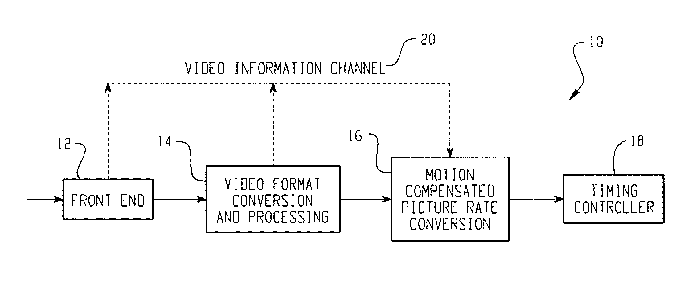
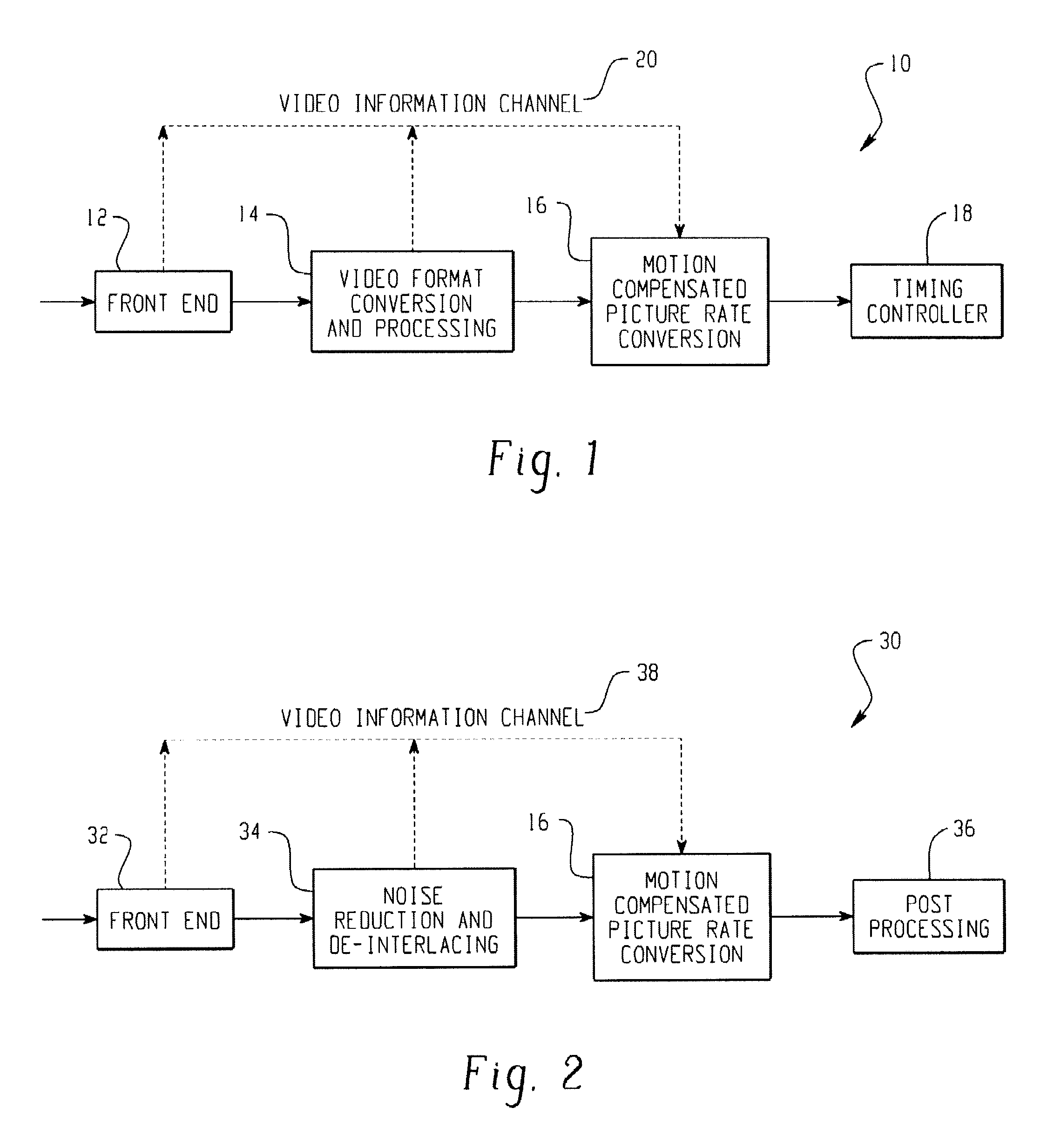
[0039]FIG. 1 is a block diagram illustrating a motion compensated picture rate converter (MCPRC) system configuration 10. An input signal, having a discrete sequence of video frames, is input to the MCPRC system 10, which produces an up-converted, motion compensated output signal via modules 12, 14, 16, and 18 of the MCPRC system 10. Each of the modules of MCPRC system 10 is described herein. Subsequent to the up-conversion, the output signal from the MCPRC system 10 has a frame rate that is typically higher than the frame rate of the input signal. For example, the input signal may be produced from a video camera which has a picture rate of 60 Hz. This video signal may need to be up-converted using the MCPRC system 10 in order to be suitable for output on an LCD panel display having, for example, a refresh rate of 120 Hz. In general, frame rate up-conversion is achieved by injecting a pre-determined number of frames between every pair of temporally adjacent input frames. These inter...


PUM


Abstract

Systems and methods for converting a picture frame rate from a source video at a first rate to a target video at a second rate via interpolation of an intermediate frame. In one implementation, the system includes a phase plane correlation calculator including a low pass filter and a high pass filter for receiving previous frame data and current frame data where the phase plane correlation calculator is configured to generate a first motion vector based upon low pass representations and high pass representations. The system may also include a motion compensated interpolator that receives the first motion vector and an additional input motion vector and determines a final motion vector for use in interpolation. The system may further include an intermediate frame generator configured to generate the intermediate frame utilizing the final motion vector.

Description

[0001]This application claims the benefit of U.S. Provisional Application No. 61 / 051,782, filed 9 May 2008; U.S. Provisional Application No. 61 / 046,922, filed 22 Apr. 2008; and U.S. Provisional Application No. 61 / 059,524, filed 6 Jun. 2008, all of which are herein incorporated in their entirety by reference. This application is related to U.S. Non-provisional application Ser. No. 12 / 400,207 filed Mar. 9, 2009 (now U.S. Pat. No. 8,233,730), entitled “Filter Bank Based Phase Correlation Architecture for Motion Estimation” filed on the same day as this application and U.S. Non-provisional application Ser. No. 12 / 400,220 filed Mar. 9, 2009 (now U.S. Pat. No. 8,184,200), entitled “Picture Rate Conversion System for High Definition Video,” also filed on the same day as this application.FIELD[0002]The technology described in this patent document relates generally to the field of picture rate conversion, and more particularly to motion compensated picture rate conversion.BACKGROUND[0003]Typ...

Claims


Application Information

Patent Timeline
02 Jul 2013
Publication
US8477848B1
IPC
H04N7/18
CPC
H04N7/014; H04N19/521; H04N19/176; H04N5/145
Inventors
PATANKAR, KAUSTUBH MILIND; NAMBOODIRI, VIPIN